


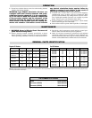

Regular Oil Heaters
Dimensions (In.)
Model Volts Phase kW W/In
2
ABC
NWHO-61215 240 or 480 3 Δ 12 23 41-3/4 30 11-3/8
NWHO-61515 240 or 480 3 Δ 15 23 48-3/4 37 14-1/8
NWHO-62015 240 or 480 3 Δ 20 23 60-1/4 48-1/2 20-5/8
NWHO-62515 240 or 480 3 Δ 25 23 73-5/8 61-7/8 27-5/16
NWHO-63015 240 or 480 3 Δ 30 23 86-5/8 74-7/8 33-7/8
NWHO-60825 240 or 480 1 or 3 Δ 8 15 41-3/4 30 11-3/8
NWHO-61025 240 or 480 3 Δ 10 15 48-3/4 37 14-1/8
NWHO-61225 240 or 480 3 Δ 12 15 60-1/4 48-1/2 20-5/8
NWHO-61525 240 or 480 3 Δ 15 15 73-5/8 61-7/8 27-5/16
NWHO-61825 240 or 480 3 Δ 18 15 86-5/8 74-7/8 33-7/8
Chromalox
®
DIVISION
4
SECTION
NWHO
SALES
REFERENCE
DATE
SERVICE REFERENCE
Installation Instructions
and
RENEWAL PARTS IDENTIFICATION
PE408-4
JULY, 1990
(Supersedes PE408-3)
161-048341-001
GENERAL
INSTALLATION
© 2010 Chromalox, Inc.
Type NWHO-6
Circulation Heaters (for
Regular and Fuel Oil Heating)
The NWHO-6 series is a general-purpose regular and fuel oil
solution circulation heater intended for use indoors. It is designed
for 150 psig at 550˚F per ANSI standards.
The 6 steel-sheathed tubular elements are centered in a 5”
diameter galvanized steel heating chamber and welded to a
removable galvanized steel flange. The assembly is surrounded
by 1-1/2” insulation and sheet metal jacket.
Depending upon the order specifications, the NWHO-6 may
or may not be factory equipped with an AR or other Chromalox
thermostat. (Note: UL listed models are factory pre-set with a
212˚F limit stop.) Such thermostats function to control outlet tem-
peratures and to limit internal temperatures under abnormal flow
conditions. These controls do not fail safe.
WARNING: Users should install adequate back-up con-
trols and safety devices with their electric heating equip-
ment. Where the consequences of failure may be severe,
back-up controls are essential. Although the safety of the
installation is the responsibility of the user, Chromalox
will be glad to make equipment recommendations.
Caution: Hazard of Electric Shock. Disconnect all
power before installing heater.
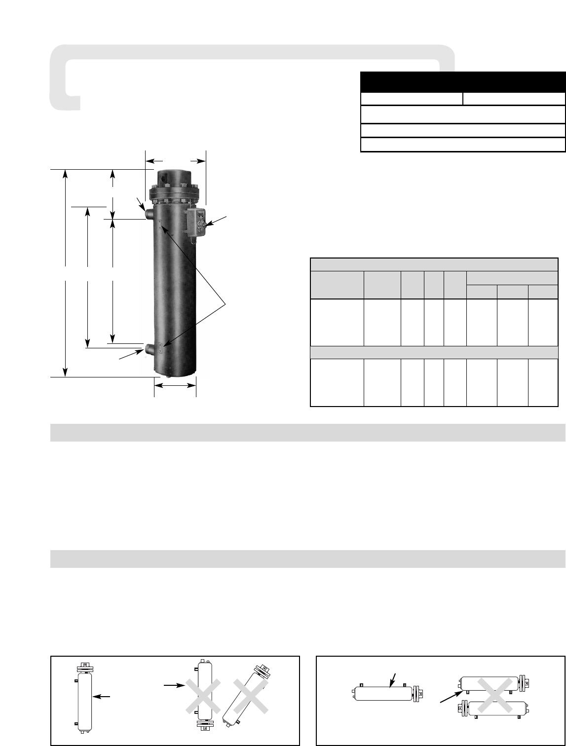
1. Vertical Mounting (Preferred) —
When the heater is vertically mounted, the terminal housing will
be at the top of the heater. The inlet pipe will be located on the side
near the bottom of the heater and the outlet pipe at the top.
The axis of the chamber will be in a vertical position as in the
photo above and as in Figure A.
Note: A drain pipe located at the bottom of the heater should be pro-
vided and enough room left, when mounting heater, to allow draining
the heater.
2. Horizontal Mounting (Optional) —
When mounting heater horizontally, inlet and outlet pipes must
be up. In any other position, heater cannot be purged of air, and
elements may be seriously damaged. (See Figure B.)
Incorrect
Correct
Figure A — Vertical Mounting
Figure B — Horizontal Mounting
Correct
Incorrect
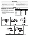
A
C
25”
B
8-5/8
16-1/16
Thermostat
Type AR
Mounting Lugs
3/8” - 16
Threaded Holes -
1-1/2” Deep
1-1/4” Centers
2” Pipe Inlet
2” Pipe
Outlet
1-3/8” Conduit
Openings
Specifications — Table A
Fuel Oil Heaters