WIRING
WARNING: Hazard of Shock. Any installation involving
electric heaters must be effectively grounded in
accordance with the National Electrical Code to elim-
inate shock hazard.
1. Electrical wiring to heater must be installed in accordance with the
National Electrical Code and/or local electrical codes by a quali-
fied person as defined in the NEC.
2. When element wattages are not equal, heaters must not be con-
nected in series.
3. Electrical wiring to heater should be connected in rigid conduit or
in flexible hose to keep corrosive vapors and liquids out of the ter-
minal housing. If high humidity is encountered, the conduit should
slope down away from the heater.
4. If flexible cord is employed, a watertight connector should be used
for entry of the cord into the terminal housing. Outdoor applica-
tions require liquid-tight conduit and connectors.
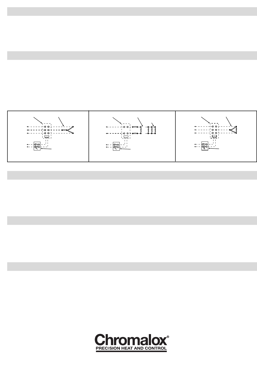
5. Bring the power line wires through the opening in the terminal
housing. Connect line wire as shown in Figures 3 through 5.
NOTE: Dotted lines indicate “customer furnished.”
OPERATION
1. Do not heat materials that are corrosive to the heating element
sheath or chamber. For water heating service, condensate drain
may be provided from bottom of chamber. Check factory.
2. Terminal ends of heater must be protected from drippings, con-
densation spray or direct spill-over of material whose presence at
the terminals may damage heater electrical insulation. Liquid-tight
terminal housings are available to protect heater. Check with Local
Chromalox Sales representative.
3. If foreign material is carried by the gaseous flow, install suitable
filters in the inlet pipe to the heater.
4. Do not allow heater to operate when fluid flow is interrupted.
MAINTENANCE
WARNING: Hazard of Shock. Disconnect all power
before servicing heater.
1. Remove heating element assembly periodically to check heater
sheath for corrosion or excessive oxidation. Correct operating con-
ditions to minimize sheath deterioration.
2. Periodically check temperature control and limit control operation
to insure accurate and safe process operation.
3. Check all electrical connections periodically and retighten connec-
tions which may have loosened in service. Replace wire terminals
which show signs of oxidation which would interfere with estab-
lishment of reliable electrical connections.
RENEWAL PARTS IDENTIFICATION
Thermostat AR-215 60-250˚F....................................300-048518-013
2150 N. RULON WHITE BLVD., OGDEN, UT 84404
Phone: 1-800-368-2493 www.chromalox.com
3 Pole Contactors
3 Heating Elements
Line
Control
Volts
Thermostat
2 Pole Contactors
1, 2 or 3 Heating Elements
in Series
Line
Control
Volts
Thermostat
or Parallel
3 Pole Contactors
3 Heating Elements
Line
Control
Volts
Thermostat
Figure 3
For 1-Phase WYE Heaters
Figure 4
For 1-Phase Heaters
Figure 5
For 3-Phase Delta Heaters
TA - U0 - EF
Litho in U.S.A.
INSTALLATION
5. DANGER: Hazard of Fire. Provide minimum of 6” spacing
from a chamber and related piping to nearest combustible materi-
al. Avoid operation of heater near combustible fluids or in com-
bustible vapor or gas laden atmosphere.
6. Provide adequate space at terminal end to permit withdrawal of the
heater from chamber should servicing be required.
7. If two or more heaters are needed to provide the needed heating
capacity, arrange them for series water flow.
8. DANGER: Possible Explosion. A pressure relief valve
should be provided by customer at outlet of vessel. There should
be no other valving between vessel and valve.
Limited Warranty:
Please refer to the Chromalox limited warranty applicable to this product at
http://www.chromalox.com/customer-service/policies/termsofsale.aspx.


