MULTI-FUNCTION DOOR CONTROL PANEL
Installation Instructions Model 945CB
Children operating or playing with a garage
door opener can injure themselves or others.
The garage door could close and cause
serious injury or death.
Install the door control (or any additional push
buttons) out of the reach of children and away
from all moving parts of the door and door
hardware,
but where the garage door is visible.
Do not allow children to operate the push
button(s) or the remote control transmitter(s).
A moving garage door could injure someone
under it.
Activate the opener only when the
door is properly adjusted, you can see it
clearly, and there are no obstructions to door
travel.
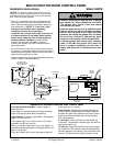
• Strip 1/4" of insulation from one end of the bell wire;
connect the wire to the two screw terminals on the
back of the door control panel as follows: white to 2
and white/red to 1. (NOTE: If "Lock" and "Light"
buttons do not function after completing
installation, reverse the connections.)
• Locate the door control within sight of the door at
a minimum height of 5 feet where small children
cannot reach, and away from all moving parts of
the door and door hardware. Fasten the Door
Control Panel securely with 6ABx1" screws. If
installing into drywall, drill 5/32" holes and use the
anchors provided.
• Run the bell wire up the wall and across the ceiling to
the opener. Use insulated staples to secure the wire in
several places. Be careful not to pierce the wire with a
staple, thereby resulting in a short.
• Connect the bell wire to the opener terminal screws as
follows: white to 2 and white/red to 1.
WARNING
NOTICE: To ensure the proper functioning of your new
Garage Door Opener, please remove all old or previous
push buttons/wall control panels. Use only the enclosed
door control for proper operation.
Opener
Terminal
Screws
2-Conductor
Bell Wire
Antenna
Back Panel
of Opener
RED-1
WHT-2
BLK-3
H
I
G
H
L
O
W
N
O
RM
A
L
UP FORCE DOWN FORCE
H
I
G
H
L
O
W
N
O
RM
A
L
PART NO: Nº DE PIÈCE:
D.O.C. / M.D.C. CERT. NO.
FCC ID
THIS DEVICE COMPLIES WITH FCC RULES PART 15
SEE OWNER'S MANUAL
zlh lkchy l cagv ,vbcjdu dkcid sac ccxb askjhdoc lkjhoi
`hoic zjh zjh cc aiu ickck c xzckjckuc czkzxkkcc
ASSEMBLED IN MEXICO 132C1998-1
askjhdoc lkjhoi `hoic zjh zjh cc aiu ickck c xzckjckuc
czkzxkkcc kkjhzxkjhzckyc . jh c zjhxckjc cliyvn ckjc
zlh lkchy l cagv ,vbcjdu dkcid sac ccxb askjhdoc lkjhoi
`hoic zjh zjh cc aiu ickck c xzckjckuc czkzxkkcc
kkjhzxkjhzckyc . jh c zjhxckjc cliyvn ckjc zlh lkchy l
cagv ,vbcjdu dkcid sac ccxb askjhdoc lkjhoi `hoic zjh
Door Control
Push Bar
LIGHT
LOCK
Multi-Function
Door Control Panel
Light Button
Lock Button
-2
-1
Multi-Function
Door Control Panel
Terminal Screws
2-Conductor
Bell Wire
© 1994, The Chamberlain Group, Inc.
114A1849 All Rights Reserved Printed in Mexico
The Door Control Push Bar: Press to open or
close the door.
Press again to
reverse
the door during the closing
cycle or to
stop
the door while it's opening.
Light Feature: Press the Light button. If the opener
light is
off,
it will turn
on.
If the opener light is on, (even in the 4-1/2 minute
automatic cycle) it will turn
off.
But if you use the Light button to turn the light(s)
on
and then activate the opener, the light(s) will turn
off
after 4-1/2 minutes.
The Light Feature will not turn the opener lights off
when the door is in motion.
Lock Feature: Designed to prevent operation of
the door from portable remote controls. However,
the door will
open
and
close
from the Door Control
push bar and from the Keylock and the Keyless
Entry Accessories.
To activate: Press and hold the Lock button for
2 seconds. The push bar indicator light will flash as
long as the Lock is
on
.
To turn off: Press and hold the Lock button again
for 2 seconds. The indicator light will stop flashing.
Normal operation will resume. The Lock feature will
also turn off whenever the "Smart" button on the
Operation of the Multi-Function Door Control Panel