


1
APPLICATION
Used to mechanically release single or bi-part sliding fire doors
from the door operator. A fusible link holds a cylindrical weight
attached to the door release. When the link melts, the weight
drops and releases the door. This modification is for use with SD
and GSD operators.
NOTE:
•
May not meet all building or regulatory codes; please consult
factory for additional specifications.
• Refer to door manufacturer for proper installation and operation
of door.
FUSIBLE LINK MODIFICATION
655502 "Single" and
655503 "Bi-Part"
Sliding Door Operators
PACKING LIST
DESCRIPTION 655502 655503
Key Hole Bracket 1 2
Fusible Link Bracket 1 2
Sash Chain 2 4
Fusible Link 1 2
"S" Hook 5 10
Eye Bolt 5/16" 1 2
Key Ring 1-1/4" 1 2
Hex Bolt 1/4-20 x 3" 8 16
Flange Nut 1/4" 8 16
Flange Nut 5/16" 1 2
Key Ring 5/8" 2 4
Weight Guide 1 2
Weight 1 2
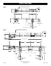
FUSIBLE LINK INSTALLATION
INSTALLATION
1. Disconnect power to operator.
2. Mount chain retaining bracket to door approximately 4'
above the floor and 2" off centerline of door (Figure 1).
3. Attach eye bolt to lower slot on disconnect assembly
(Figure 1).
4. Secure the fusible link chain mounting bracket to the upper
leading edge of the door (6 - 12" below the top) so that the
fusible link will be in the door opening when the door is
open (Figure 1).
5. Thread the fusible link chain through the eye bolt, then
through the eyelet in the weight mechanism, and then up
through the bottom of the disconnect pin.
6. Raise the weight to approximately 3' from floor level and
engage the chain in the slot of the chain retaining bracket.
7. Couple the chain to itself around the weight so that the
chain cannot move through the eyelet in the weight.
8. Disengage the chain and allow the weight to hang from the
fusible link.
9. Leave a small amount of slack between the weight and the
disconnect pin and fasten a key ring to the link on each side
of the disconnect pin so that the chain cannot pass through
the hole.
10. Cut off any excess chain leaving 6" to hang below the chain
retaining bracket.
11. Fasten the key ring 1-1/4" to end of chain.
12. Mount the weight guide to the door with the weight
protruding 3 - 4" above the guide (Figure 1).
BI-PART DOORS
Install the second fusible link assembly on the second door
following the steps outlined above. Be sure that one link is hung
lower than the other so they do not interfere with each other
when the doors are fully closed (Figure 2).
TEST
Test the fusible link disconnect installation as follows. Manually
remove the fusible link from the bracket and allow the weight to
pull down on the disconnect pin. Verify that the door is
disconnected and moves freely. If necessary, adjust spring on
disconnect assembly by moving the top shaft collar up or down.
Reconnect power to operator.
To prevent possible SERIOUS INJURY or DEATH, disconnect
electric power to operator BEFORE installing.
ALL electrical connections MUST be made by a qualified
individual.
WARNING
CAUTION
WARNING
WARNING