


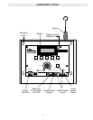

RELAY OUTPUT
N.O. contacts
SERIAL PORT
12
SELECT
24
VAC
12/24
VOLTS
AC/DC
EXT.
GRANT
SWITCH
N.E.C. CLASS 2
WIRING ONLY
❷
❷
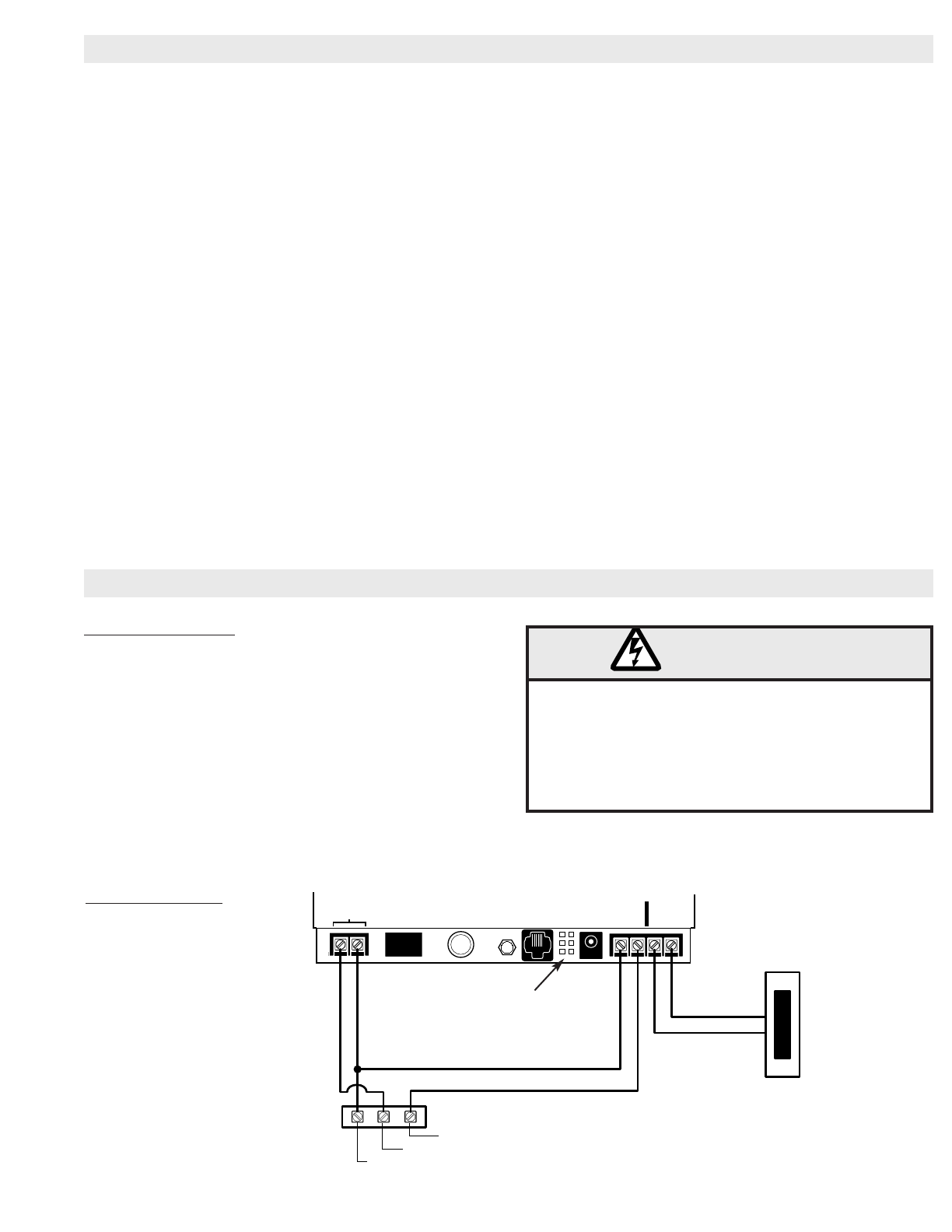
Radio Power
Common
Push Button
Doorbell
Button
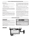
Voltage select jumpers:
Place jumpers on bottom 2 pins for 24V operation
Place both jumpers on top 2 pins 12v operation
The ACRx 2 uses low voltage wiring only. Attach the
ACRx only to circuits or devices that are NEC Class 2
(less than 37VAC). Do not run wires to or from the
ACRx 2 in any conduit or box where there are AC
supply (120VAC) circuits. Failure to follow this
warning could result in electrical shock or fire and
damage to the ACRx 2.
WARNING
2
Mounting the Box
Choose a location for the ACRx 2 1025 control box which is:
• Protected from tampering
• As close to the approaching vehicles as possible for best
reception.
• Protected from moisture.
• Suitable for permanent attachment by mounting screws.
• Accessible to necessary wiring.
Hold the ACRx 2 control box in its intended mounting
location. Make sure the cover opens freely, with the display and
controls at a comfortable height and angle for viewing and use.
Use the holes in the ACRx 2 box for marking and drilling
attachment holes.
Antenna Placement
For best range, placement of the antenna is crucial. Follow
these guidelines for best results.
•Make sure there is no interfering signal an the same channel as
the ACRx 2. You can monitor channel activity with the
Liftmaster M-18 Test Set. On-channel interference is not only
due to transmitters, but can also be caused by computing
devices, security systems, and other nearby electronic devices.
Power invertors and battery chargers are known sources of
interference.
Wiring requirements
Power can be provided with an 85LM wall mount transformer or
Radio Power from a gate operator (17 to 37 V AC/DC at 150
mA or 12 VDC at 200 mA minimum.)
Using an 85LM wall mount transformer: Install the voltage
select jumpers (J4 & J6) in the 24v position and plug the
transformer jack into the receptacle to the right of the voltage
jumper. Wire the relay contacts to Push Button and Common as
shown in the wiring diagram
Using gate/door operator power: Install the voltage select
jumpers (J4 & J6) in the position that matches the power
supplied by the operator. Wire ACRx 2 to the operator as
shown in the wiring diagram.
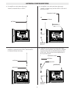
• The ACRx 2 antenna system can be configured in several
ways. Each installation is different, so there is no best antenna
system. Try the different configurations of antenna placement
and amplifier until the best range is encountered. Do this
BEFORE hard -mounting the antenna and permanently routing
the cable.
The typical antenna configurations are as follows on page 3:
• The antenna must not be next to, or enclosed in, metal.
• Place the antenna outside of any housing, box, or building,
even if the housing is not made of metal. Non-metallic
structures can contain conduit, metallic-foil insulation, or be
painted with metallic paint.
• Place the antenna as high as possible, in sight of the expected
location of the transmitters. This is very important.
• Consider the direction from which the transmitters will be
used. Place the antenna so that there are no structures or metal
obstructions between the transmitters and receiving antenna.•
Make certain that the amplifier, if used is oriented correctly.
The label indicates the end of the amp which must be connected
to the ACRx 2 or to the cable leading to the ACRx 2. The amp
will not work properly if installed backwards.
• If longer coaxial cable is needed, do not splice cables together.
Instead, purchase a ready-made cable of the desired length from
a radio/tv store. Use 75-ohm cable with CATV connectors
(also called type “F” connectors).
WIRING INSTRUCTIONS
WIRING DIAGRAM
ACRX & ANTENNA MOUNTING INSTRUCTIONS