


Installation Step 7
Install the Door Control and
Connect all Wiring
17
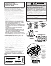
DO NOT CONNECT TO LIVE ELECTRICAL WIRING. CONNECT
ONLY TO 24 VOLT LOW VOLTAGE WIRES. CONNECTION TO
LIVE WIRES OR HIGHER VOLTAGE MAY CAUSE SERIOUS
INJURY FROM SHOCK, BURN OR ELECTROCUTION.
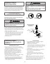
Children operating or playing with a garage door opener can
injure themselves or others.
The garage door could close and
cause serious injury or death. Do not allow children to operate
the push button or the remote control transmitter.
A moving garage door could injure someone under it.
Activate
the opener only when the door is properly adjusted, you can
see it clearly, and there are no obstructions to door travel.
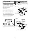
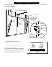
Locate the door control within sight of the door at a minimum
height of 5 feet where small children cannot reach, and away
from all moving parts of the door and door hardware.
The door control is typically attached directly to the wall. If
installing into drywall, drill 5/32" holes and use the anchors
provided. For pre-wired installations (as in new home
construction), the multi-function door control can be mounted
to a standard single gang box.
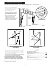
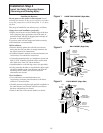
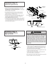
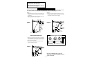
1. Strip 1/4" of insulation from one end of the bell wire and
connect it to the two screw terminals on the back of the door
control by color: white to 2 and white/red to 1. (Fig. 1)
2. Lighted door control: Fasten to wall with 6ABx1-1/2" self-
tapping screws.
Multi-function: Remove the white cover by gently pushing
both thumbs against upper corners of cover on the back side
of the door control (Fig. 2). Fasten with 6ABx1-1/4" self-
tapping screws (standard installation) or 6-32x1" machine
screws (pre-wired installation) as follows: (Fig. 3)
• Install bottom screw, allowing 1/8" to protrude from the wall.
• Position bottom of door control over screw head and adjust
for snug fit.
• Install top screw with care to avoid cracking plastic
housing. Do not overtighten.
• Replace cover by inserting bottom tabs and snapping into
place. To remove cover after mounting, gently pry at top
with paper clip or small flat head screwdriver.
NOTE: After installation, a green indicator light behind the
cover will indicate proper connection. If not lit, the Lock and
Light features will not function (reverse wires to correct).
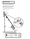
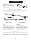
3. Standard installation only: Run bell wire up wall and
across ceiling to opener. Use insulated staples to secure wire
in several places. Be careful not to pierce the wire with a
staple, creating a short. If your access door is near the
garage door, you may run this wire with the Safety Reversing
Sensor wires along the top of the rail. See page 14.
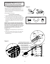
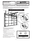
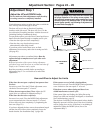
4. Remove Control Center door on right panel of opener to
access the terminal screws.
5. Thread all wires through the opening at the base of the drive
shaft cover (Fig. 4).
6. Insert the remaining wire through the hole in the power unit
and strip 1/4" of insulation from each set of wires.
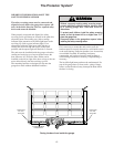
7. Connect door control wire to the opener terminal screws:
white to 2 and white/red to 1.
8. Connect sensor wires to the opener terminal screws: white to
2 and white/black to 3.
9. Attach the User Safety Instruction label to the wall near the
door control, and the Maintenance Instruction label in a
prominent location on the inside of the garage door.
Page 28 explains how to operate the opener using the door
control.
WARNINGWARNING
Do NOT connect the power and operate the opener at
this time. See Step 9 on page 18.
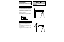
Outside Keylock connections (see Accessories)
To opener terminal screws: white to 2; white/red to 1
OPENER TERMINAL SCREWS
(In Control Center)
Sensor
Connections
Door Control
Connections
(dotted line)
1
2
3
To
Door
Control
To
Sensors
Terminal
Screws
Control
Center
1 2 3
Figure 4
WIRING TO
CONTROL CENTER
1. INSERT WIRES
THROUGH
OPENING IN
DRIVE SHAFT
COVER
2. PUSH WIRING
THROUGH HOLE IN
CHASSIS
(ABOVE CONTROL
CENTER) AND
CONNECT TO
OPENER TERMINAL
SCREWS
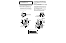
6ABx1-1/2" Screw
Lighted Door Control Button
Dry Wall
Anchors
Insulated
Staples
6AB x 1-1/4" Screw
Multi-function (std installation)
6-32 x 1" Screw
Multi-function (pre-wired)
Hardware Shown Actual Size
LOCK
LIGHT
To Replace,
Insert Bottom Tabs First
STANDARD
INSTALLATION
2
1
RED
WHT
To Replace,
Insert Bottom Tabs First
24 Volt
2-Conductor
Bell Wire
LOCK
LIGHT
Lighted
Door Control
WHT
2
RED
1
Multi-Function
Door Control
2
1
RED
WHT
Terminal
Screws
PRE-WIRED INSTALLATION
REMOVE COVER
Figure 1
Figure 2
Figure 3