18
Vermont Castings EWF36A
20005167
Operation
Attach Handles
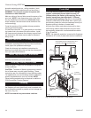
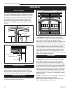
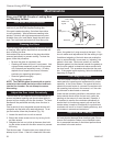
The fallaway handles are used to open and close the
front doors. Remove after each use so they will not get
hot. Keep in convenient location for each use. (Fig. 26)
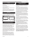
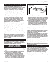
Assemble the primary air control and damper handles
by passing the 3³⁄₈” screw through the ceramic shaft
and into the bright metal hub. Tighten carefully until
snug. Do not overtighten. Ceramic handle could crack.
(Fig. 27)
5167
EPA36
cover
3/02
FP1397
Fig. 26 Insert fallaway handles into door handle stubs.
Steel Handle
Fallaway Handle
EWF36A Controls
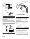
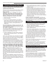
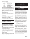
Three controls regulate the performance of the
EWF36A fireplace: A primary air control supplies oxy-
gen for the fire, the damper directs air flow within the
fireplace and a variable-speed fan control, or rheostat,
regulates the warm air flow into the room. (Fig. 28)
Primary Air Control
A single air control regulates the amount of heat the fire
will produce and how long it will burn.
FP1396
EWF handles
8/14/03 djt
FP1396
Fig. 27 Assemble primary air control and damper handles.
Screw
Ceramic Shaft
Metal Hub
The primary air control is located in the upper left
corner of the unit. (Fig. 26) It is the primary source of
air for starting, maintaining, and reviving the fire.
Generally, more air entering the fireplace makes the fire
burn hotter and faster, while less air prolongs the burn.
The air supply is open to the maximum when the control
lever is rotated clockwise, and closed when rotated
counterclockwise. To vary the burn rate, adjust the con-
trol to the desired position in between these extremes;
opening the primary air control makes the unit burn
hotter. Closing the control slows the unit down. You may
adjust to any position you desire.
The Damper
The damper directs air flow within the fireplace.
The damper is operated by moving the lever located
in the upper right corner of the unit. It has two posi-
tions: Open to start or revive the fire and closed, for
normal operation and to control burn rate. The damper
is open when the lever is fully rotated counterclockwise
and pulled out and closed when pushed in. When the
damper is in the open position, with the lever pulled out,
and rotated fully in the clockwise direction, the handle
can ‘telescope’ back without closing the damper or any
damper movement. There are no intermediate settings
for the damper.
NOTE: Full clockwise or counterclockwise movement of
the damper handle is approximately 50°.
NOTE: Always open the damper before opening the
doors. Close damper to set burn rate.
FP1204
EPA36
controls
3/20/02 djt
Primary Air Control
FP1203
Fig. 28 EWF36A controls.
Damper


