


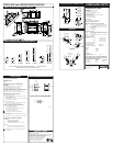


FIREPLACE and VENTING SPECIFICATIONS
VENT SECTIONS and OFFSETTING ELBOWS
NOTE: THE INSTALLED LENGTH OF ANY VENTING SECTION IS 1
1/2
” LESS THAN ITS TOTAL
LENGTH, EXCEPT FOR THE LAST SECTION INSTALLED.
12"
305mm
24"
610mm
36"
914mm
48"
1219mm
7TDVP8
7TDVP12
7TDVP24
7TDVP36
7TDVP48
7TDVP1218
7TDVP3564
8"
203mm
7"
178mm
35"
889mm
64"
1626mm
10"
254mm
18"
457mm
TRIBUTE 36CDVXR REAR VENT GAS FIREPLACE
Tribute 36CDVXR
FEATURES:
• 36" Tribute Direct Vent Gas Appliance
• 14,700 to 21,000 BTU/hr. input
• 18"Gas Inlet Flex Line with Shut-Off Valve
• 2 Piece Log Set Fastened
• Embossed Refractory
• Attached 17' Low Voltage Wire Connected to Valve for
Remote Operation Hook-Up
• Includes Electrical Recepticall
Accessories:
FK12 - Fan and Cord (160cfm) (for RN/RP only)
RC1/RC2 - Universal Remote Controls
IMTFK - IMT Thermostat w/ Face Plate
Dedicated Tribute DV Venting Components:
7TCRVT - Rear Vent Kit includes: Rigid Flue Assembly, Hot
Touch Termination which telescopes between 7" and
13" and Firestop
7TCDV45KT - Flex Pipe Assembly extends 13" to 32", Firestop
& Termination
7TCDV90 - 90 Degree Elbow
Bulk Flex Vent Kits*
7FDVCK - Bulk Flex Connector Kit(Includes: 10 4" Clamps
and 10 7" Clamps to secure the flex vent to the fireplace
and termination)
7FDVSPK - Bulk Flex Spacer Kit (Includes: 10 Spring Spacers)
VSK7 - Vertical Vent Kit
BURNER SYSTEM:
• Capacity – Natural: 21,000 BTU/HR Max.
14,700 BTU/HR Min.
– Propane: 21,000 BTU/HR Max.
15,750 BTU/HR Min.
• Fuel - Natural or Propane Gas
Clearance to Combustibles:
Top of Unit to Ceiling 36” (914 mm)
Front of Unit of Combustibles 36” (914 mm)
Appliance
Top 0” (0 mm)
Bottom 0” (0 mm)
Side 0” (0 mm)
Back 0” (0 mm)
Venting
Concentric sections of DV Vent
Top, bottom & sides 1” (25 mm)
NOTE: Hood must be permanently installed with
three (3) sheet metal screws supplied in Fireplace.
Gas Inlet and Manifold Pressures
Natural LP (Propane)
Inlet Minimum 5.5” w.c. 11.0” w.c.
Inlet Maximum 14.0” w.c. 14.0” w.c.
Manifold Pressure 3.5” w.c. 10.0” w.c.
9
1/4
"
7
1/4
"
9
1/4
"
90°
7"
13"
9
1/4
"
90
°
13"
7
1/4
"
13"
17
"
OFFSET
235mm
235mm
178mm
184mm
330mm
330mm
335mm
330mm
184mm
OFFSET w/2-90°
Back to Back
FIREPLACE FACTS
The Fireplace Facts Information Sheets are
for quick reference only and are subject
to change without notice. Actual fi replace
instructions must abide by specifi cations
provided with each product.
CONTEMPORARY TERMINATIONS
7TDV45
7TDVRT90
11"
7
3/8
"
45°
45°
7
3/8
"
OFFSET w/2-45°
Back to Back
45°
7
3/8
"
188mm
188mm
188mm
FP890
FP889
ELBOWS
7"
7TDVSKV
7"
7TDVSKS
32"
6
1/2
"
813mm
127mm
19"
16"
482mm
406mm
165
mm
5
"
7TDRVT
7TRVT
13.25”
10.5”
9.75”
11.5”
REV. 09/07
FLUE SYSTEM
FLUE SYSTEM
36CDVR Certified to - ANSI Z21.88-2005 / CSA 2.33-2005
Vented Gas Fireplace Heaters
PRODUCT LISTING
7” Coaxial Direct Vent System
SPECIFICATIONS:
• 7” O.D.
• 4” I.D.
MINIMUM CLEARANCE TO COMBUSTIBLE
MATERIAL
a) Rear Wall Vent Applications 2” top, 1” Sides & Bottom
b) Vertical Side Wall Applications 1” to All Sides
c) Vertical thru the Roof Applications 1” to All Sides
MINIMUM COMBUSTIBLE WALL/FLOOR OPENINGS
a) 9 3/8” W x 9 3/8” H for Rear Wall Vent Applications
b) 9 3/8” W x 9 3/8” H for Vertical Side Wall/Vertical Applications
MAXIMUM INSTALLATION LENGTHS
a) Rear Wall Vent Applications
• 20” to 32” outside wall, and of vent outlet thru wall to be 24 1/4”
up from floor, use 7TCDV45FT
• 7” to 13” straight out
• Corner Installation: 7TCDV45KT must be used. Vent outlet and
thru wall must be 29 1/2” from floor
b) Vertical Side Wall Applications
20ʼ (6 m) Horizontal Vent Length with 7.5ʼ (2.29 m) vertical rise
*Refer to manual for alternative venting distance
VERTICAL THRU THE ROOF APPLICATIONS
• 8ʼ (2.4 m) Minimum Vertical Rise
• 40ʼ (12 m) Maximum Vertical Rise
• 2 sets of 45° Elbows can be used in Vertical rise with 8ʼ
maximum distance between elbows
• Two 90° elbows maximum for 10ʼ (3 m)
• Horizontal can be installed in Vertical Applications
*Maximum angular variation for Vertical Sidewall/Vertical Application
in system is total of 270°
*Refer to installation manual for all venting restrictions with elbow use
TERMINATION CLEARANCES MINIMUM
a) Horizontal
12” (305 mm) above Grade Level
18” (458 mm) to Ventilated Soffit
12” (305 mm) to Unventilated Soffit
12” (305 mm) under veranda, porch, deck or balcony
b) Vertical
24” (610 mm) Above a Roof Surface and any other
obstruction within a horizontal distance of 18” (458 mm)
*Refer to installation manual for more termination restrictions and
clearance information
This appliance may be installed in an aftermarket permanently located,
manufactured home or mobile home, where not prohibited by local
codes.This appliance is only for use with the type of
gas indicated on the rating plate. This appliance is
not convertible for use with other gases, unless
a certified kit is used. The CDVXR has been
approved for mobile home installations.
VERTICAL SIDEWALL INSTALLATION
Rnd.
Vertical Side Wall Installations
Framing
Detail
"
9 3/8”
(240mm)
9 3/8”
(240mm)
Fireplace Hearth
Venting Opening for Combustible Wall
Opening for Noncombustible Wall
V0584-100
7 1/2”
(190mm)