


Manufacturer reserves the right to discontinue, or change at any time, specifications or designs without notice and without incurring obligations.
PC 111 Catalog No. 534-80082 Printed in U.S.A. Form 48/50H,T-15SI Pg 1 8-01 Replaces: 48/50H,T-2SI
Book 111444
Tab 1a1b5a5a6a6b
Installation, Operation, and
Troubleshooting Instructions
SAFETY CONSIDERATIONS
Read these instructions entirely before modifying the base
rooftop unit.
Installation and servicing of air-conditioning equipment can
be hazardous due to system pressure and electrical compo-
nents. Only trained and qualified service personnel should
install, repair, or service air-conditioning equipment.
Untrained personnel can perform the basic maintenance
functions of replacing filters. All other operations should be
performed by trained service personnel. When working on air-
conditioning equipment, observe precautions in the literature,
tags and labels attached to the unit, and other safety precautions
that may apply.
Follow all safety codes. Wear safety glasses and work
gloves. Use quenching cloth for unbrazing operations. Have
fire extinguishers available for all brazing operations.
GENERAL
The Apollo control is a relay pack which is factory wired
and mounted in the Carrier rooftop unit. The Apollo control
allows the unit to be connected to a thermostat and a communi-
cation bus. The rooftop unit can then be used as part of a
system which is controlled by devices on the communication
bus. The thermostat and communication bus wiring must be
field installed.
Carrier TEMP System —
The Carrier TEMP System
usually consists of more than one thermostat and can be ex-
panded to meet whatever number of single zone systems are
required.
The TEMP System thermostat maintains proper tempera-
tures by controlling the amount of heated or cooled air supplied
to the area in which it is installed or the area it controls (if using
a remote room sensor).
Each thermostat is responsible for controlling the tempera-
ture conditions in its space. Each thermostat will maintain its
own independent occupied/unoccupied time schedule and heat-
ing (if applicable) and cooling set points. This allows the user
to program the TEMP System thermostat so that it will main-
tain different temperature ranges at different times.
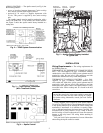
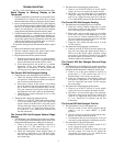
TEMP System Components —
The Carrier TEMP
System consists of one or more thermostats that communicate
by way of a communication bus. Each thermostat controls an
Apollo control which in turn controls the Carrier rooftop unit.
See Fig. 1.
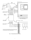
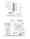
Each thermostat can be connected to others to provide com-
munication between thermostats. Only one thermostat per sys-
tem can have a timeclock that will broadcast time to the rest of
the system. See Fig. 2.
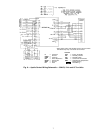
TEMP SYSTEM THERMOSTATS — The 33CSTMT-01,
or 33CSVMT-XX (with timeclock) and 33CSTM-01 or
33CSVM-XX (without timeclock) TEMP System thermostats
(see Fig. 3) have the following features:
• controls temperature to user-defined set points
• eliminates the need for external timeclocks, manual
override timer, night low limit thermostat, battery
backup, or unit time guard
• operates with 3 system switches for supply-air fan and
the unit heating (if applicable) and cooling stages
NOTE: For 33CSVM(T)-XX thermostats, the “XX” will be
either “04,” “16,” or “32.”
Before beginning any modification, make sure all power is
disconnected to the unit and locked out. Failure to discon-
nect power supply prior to servicing may result in serious
injury. All wiring must comply with applicable national
and local codes.
When removing panels from the unit, be careful not to
damage the roof or other surfaces with the panels.
Do not turn on unit power until Apollo control and thermo-
stat have been installed. Unit is shipped with loose leads
which may cause electrical shock or death.
48/50HJ004-024
50TFQ004-012, 48/50TF,TM004-014
50HJQ004-016, 48/50TJ,TM016-028
Apollo Control
*Where “XX” will be “04,” “16,” or “32.”
Fig. 1 — Carrier TEMP System Components
HVAC —
Heating, Ventilation, and Air Conditioning