


6
INSTALLATION INSTRUCTIONS
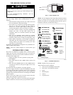
PERSONAL INJURY/UNIT OPERATION HAZARD
Failure to follow this caution may result in personal injury
and/or damage to unit components.
It is recommended to have someone assist you during the
installation of this unit because the compressor is located on
the controls side of the unit (right side) and this side will be
heavier and more awkward to manipulate.
CAUTION
!
Step 1 —Select the Best Location
A. Your room air conditioner was designed to fit easily into a
single or double hung window. However, since window
designs vary, it may be necessary to make some modifications
for safe and proper installation.
B. Make sure window and frame is structurally sound and free
from dry and rotted wood.
C. For maximum efficiency, install the air conditioner on side of
the house or building which favors more shade than sunlight.
If the unit is in direct sunlight, it is advisable to provide an
awning over the unit.
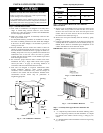
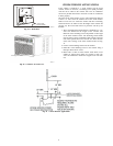
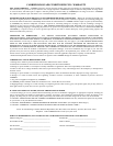
D. Provide sufficient clearance around the cabinet to allow for
ample air circulation through the unit (see Fig. 5). The rear of
the unit should be outdoors and not in a garage nor inside of a
building. Keep unit as far away as possible from obstacles and
obstructions and at least 30” above the floor or ground.
Curtains and other objects within a room should be prevented
from blocking the air flow.
E. Be certain the proper electrical outlet is within reach of the
installation. Use only a single outlet circuit rated at proper
current (see table 1 on page 4). All wiring should be in
accordance with local and national electrical codes.
F. Your unit was designed to evaporate condensation under
normal conditions. However, under extreme humidity
conditions, excess condensation may cause the basepan to
overflow to the outside. The unit should be installed where
condensation run--off cannot drip on pedestrians or
neighboring properties.
Awning
Side
obstruction
Ground
Fence,
wall, or
other
obstacle.
12” Min.
30” Min.
20”
Min.
20”
Min.
A06534
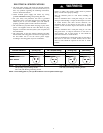
Fig. 5 --- Air Conditioner Clearances
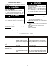
Window Opening Requirements
SIZE
MODEL
12K 14K---23K
Cabinet Size
(W/H/D)
22.8”/15.7”/24.1” 26.5”/18.5”/26.9”
Window Opening
Width
27” --- 41” 30” --- 44”
Window Opening
Height
16” 18.5”
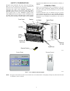
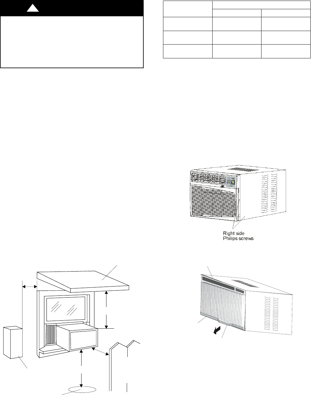
Step 2 —Preparation to Remove the Air Conditioner
Slide--Out Chassis
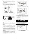
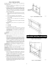
A. Remove total of ( 4) Philips screws securing the chassis t o the
cabinet. There are (2) screws on each side. The set of screws
closest to the front of the unit secure the front panel to the
cabinet. The set of screw closest to the rear of the unit secure
the cabinet to the chassis (see Fig. 6).
B. Remove the front panel assembly from the cabinet by gently
pulling it.
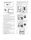
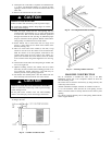
C. Grasp the pull handle at the front of the slide--out chassis and
carefully slide the air conditioner out of the cabinet (see Fig. 7).
NOTE: Screws must be reinstalled upon completion of the
window installation to secure slide--out chassis.
IMPORTANT: Please seek assistance for this procedure.
A06535
Fig. 6 --- Screw Removal
Coil
Pull Handle
Chassis
A06536
Fig. 7 --- Air Conditioner Removal
Step 3 —Assembly of the upper & lower channels to the
cabinet
A. ” L” Shaped Top Channel: Stick the double adhering seal to
the ” L” shaped top channel, and then Install the ”L” shaped
top channel to the cabinet as shown in Fig. 8 using (5) 1/4”
screws.
B. ”n” Shaped Bottom Channel installed as shown in Fig.8 using
(4) 1/4” screws.