


Manufacturer reserves the right to discontinue, or change at any time, specifications or designs without notice and without incurring obligations.
PC 111 Catalog No. 535-004 Printed in U.S.A. Form 50R-2SI Pg 1 8-02 Replaces: New
Book 1 4
Ta b 5 a 5 a
Installation, Start-Up, and
Service Instructions
CONTENTS
Page
SAFETY CONSIDERATIONS . . . . . . . . . . . . . . . . . . .1,2
GENERAL. . . . . . . . . . . . . . . . . . . . . . . . . . . . . . . . . . . . . . . . 2
INSTALLATION . . . . . . . . . . . . . . . . . . . . . . . . . . . . . 2-14
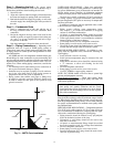
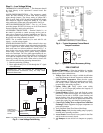
Step 1 — Check Jobsite. . . . . . . . . . . . . . . . . . . . . . . . 2
Step 2 — Check Unit . . . . . . . . . . . . . . . . . . . . . . . . . . . 2
• STORAGE
• PROTECTION
• INSPECT UNIT
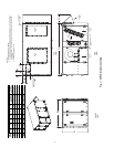
Step 3 — Location of Unit . . . . . . . . . . . . . . . . . . . . . . . . 3
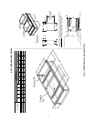
Step 4 — Mounting the Unit . . . . . . . . . . . . . . . . . . . . . . 6
Step 5 — Condensate Drain . . . . . . . . . . . . . . . . . . . . . . 6
Step 6 — Piping Connections . . . . . . . . . . . . . . . . . . . . 6
• WATER LOOP APPLICATIONS
• GROUND-WATER APPLICATIONS
• GROUND-LOOP APPLICATIONS
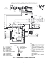
Step 7 — Electrical Wiring. . . . . . . . . . . . . . . . . . . . . . . . 7
• SUPPLY VOLTAGE
• 208-VOLT OPERATION
• BLOWER SELECTION
Step 8 — Low Voltage Wiring. . . . . . . . . . . . . . . . . . . . 14
• THERMOSTAT CONNECTIONS
• WATER FREEZE PROTECTION
• AIR COIL FREEZE PROTECTION
• ACCESSORY CONNECTIONS
• WATER SOLENOID VALVES
PRE-START-UP . . . . . . . . . . . . . . . . . . . . . . . . . . . . . . . .14,15
System Checkout. . . . . . . . . . . . . . . . . . . . . . . . . . . . . 14
FIELD SELECTABLE INPUTS . . . . . . . . . . . . . . . .15,16
C Control Jumper Settings . . . . . . . . . . . . . . . . . . . . 15
C Control DIP Switches . . . . . . . . . . . . . . . . . . . . . . . 15
D Control Jumper Settings . . . . . . . . . . . . . . . . . . . . 15
D Control DIP Switches . . . . . . . . . . . . . . . . . . . . . . . 15
D Control Accessory Relay Configurations . . . . . 16
Water Valve (Slow Opening) . . . . . . . . . . . . . . . . . . . 16
Outside Air Damper (OAD) . . . . . . . . . . . . . . . . . . . . 16
START-UP . . . . . . . . . . . . . . . . . . . . . . . . . . . . . . . . . . . . 16-18
Operating Limits . . . . . . . . . . . . . . . . . . . . . . . . . . . . . . . . 16
Scroll Compressor Rotation. . . . . . . . . . . . . . . . . . . . . 17
Unit Start-Up Cooling Mode . . . . . . . . . . . . . . . . . . . . . 17
Unit Start-Up Heating Mode . . . . . . . . . . . . . . . . . . . . . 17
Flow Regulation. . . . . . . . . . . . . . . . . . . . . . . . . . . . . . . . . 17
Flushing . . . . . . . . . . . . . . . . . . . . . . . . . . . . . . . . . . . . . . . . 17
Antifreeze . . . . . . . . . . . . . . . . . . . . . . . . . . . . . . . . . . . . . . . 18
Cooling Tower/Boiler Systems . . . . . . . . . . . . . . . . . . 18
Ground Coupled, Closed Loop and Plateframe
Heat Exchanger Well Systems . . . . . . . . . . . . . . . . 18
Page
OPERATION. . . . . . . . . . . . . . . . . . . . . . . . . . . . . . . . . . . . . 19
Power Up Mode . . . . . . . . . . . . . . . . . . . . . . . . . . . . . . . . . 19
Units with Aquazone™ Complete C Control . . . . . 19
Units with Aquazone Deluxe D Control. . . . . . . . . . 19
SYSTEM TEST . . . . . . . . . . . . . . . . . . . . . . . . . . . . . . . .19,20
Test Mode. . . . . . . . . . . . . . . . . . . . . . . . . . . . . . . . . . . . . . . 19
Retry Mode. . . . . . . . . . . . . . . . . . . . . . . . . . . . . . . . . . . . . . 20
Aquazone Deluxe D Control LED Indicators . . . . . 20
SERVICE . . . . . . . . . . . . . . . . . . . . . . . . . . . . . . . . . . . . . 20-22
Filters . . . . . . . . . . . . . . . . . . . . . . . . . . . . . . . . . . . . . . . . . . . 20
Water Coil . . . . . . . . . . . . . . . . . . . . . . . . . . . . . . . . . . . . . . . 20
Condensate Drain Pans . . . . . . . . . . . . . . . . . . . . . . . . . 21
Refrigerant System. . . . . . . . . . . . . . . . . . . . . . . . . . . . . . 21
Condensate Drain Cleaning . . . . . . . . . . . . . . . . . . . . . 21
Air Coil Cleaning . . . . . . . . . . . . . . . . . . . . . . . . . . . . . . . . 21
Condenser Cleaning . . . . . . . . . . . . . . . . . . . . . . . . . . . . 21
Checking System Charge . . . . . . . . . . . . . . . . . . . . . . . 22
Refrigerant Charging. . . . . . . . . . . . . . . . . . . . . . . . . . . . 22
Air Coil Fan Motor Removal . . . . . . . . . . . . . . . . . . . . . 22
TROUBLESHOOTING. . . . . . . . . . . . . . . . . . . . . . . . . 22-25
Thermistor . . . . . . . . . . . . . . . . . . . . . . . . . . . . . . . . . . . . . . 22
Control Sensors. . . . . . . . . . . . . . . . . . . . . . . . . . . . . . . . . 22
START-UP CHECKLIST . . . . . . . . . . . . . . . . . . CL-1, CL-2
SAFETY CONSIDERATIONS
Installation and servicing of air-conditioning equipment can
be hazardous due to system pressure and electrical compo-
nents. Only trained and qualified service personnel should
install, repair, or service air-conditioning equipment.
Untrained personnel can perform basic maintenance func-
tions of cleaning coils and filters and replacing filters. All other
operations should be performed by trained service personnel.
When working on air-conditioning equipment, observe precau-
tions in the literature, tags and labels attached to the unit, and
other safety precautions that may apply.
Improper installation, adjustment, alteration, service, main-
tenance, or use can cause explosion, fire, electrical shock or
other conditions which may cause personal injury or property
damage. Consult a qualified installer, service agency, or your
distributor or branch for information or assistance. The
qualified installer or agency must use factory-authorized kits or
accessories when modifying this product. Refer to the individ-
ual instructions packaged with the kits or accessories when
installing.
IMPORTANT: Read the entire instruction manual before
starting installation.
Rooftop Water Source Heat Pump Units
50RTG
TM