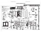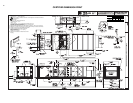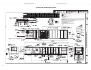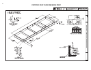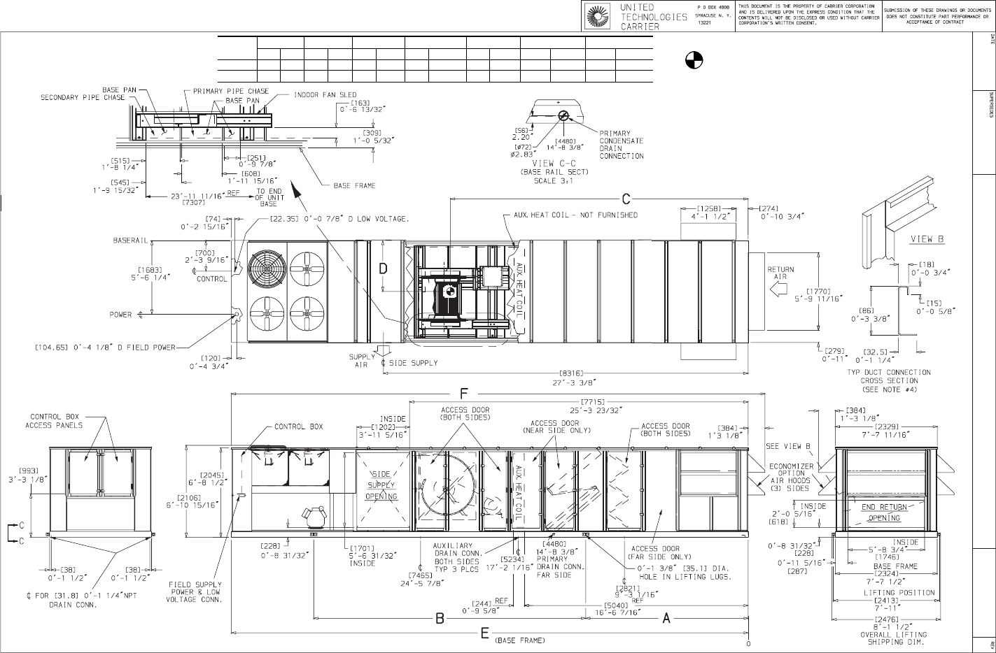
50JB054,064 (EXTENDED CHASSIS)
UNIT
SIZE
WEIGHT A B C D E F
lb kg mm ft-in. mm ft-in. mm ft-in. mm ft-in. mm ft-in. mm ft-in.
50JB054 8800 3990 2959 9-8
1
⁄
2
6940 22-9
3
⁄
4
6393 20-11
11
⁄
16
1163 3-9
25
⁄
32
11 780 38-7
13
⁄
16
12 164 39-10
7
⁄
8
50JB064 9100 4127 2959 9-8
1
⁄
2
6940 22-9
3
⁄
4
6393 20-11
11
⁄
16
1163 3-9
25
⁄
32
11 780 38-7
13
⁄
16
12 164 39-10
7
⁄
8
NOTES:
1. Dimensions in [ ] are inmillimeters.
2. Center ofGravity includeseconomizer. Unitweight doesnot include economizeror
heating coil.
3. Unit clearances:
Top — Do notrestrict condenser fans
Control Box End— 6Ј-0Љ
Sides — 6Ј-0Љ
Economizer End —6Ј-0Љ
For smaller service and operating clearances, contact Carrier Application Engineering
Department.
4. Suggested fieldconnections to be madeinside or outside of1.28 in. (32.5 mm)flange.
5. When theunit is slab mounted,plug the factory drilledauxiliary condensate drain holes.
6. Auxiliary heatingcoil is field suppliedand installed.
7. Auxiliary heatingcoil dimensions (maximum):
Length (header included),7Ј-0
1
⁄
4
Љ [2140]
Width, 0Ј-9
5
⁄
8
Љ [244]
Height, 4Ј-5
15
⁄
16
Љ [1370]
8. Economizer sidehoods are folded insideunit for
shipping.
CERTIFIED DIMENSION PRINT
7
CUT ALONG DOTTED LINE CUT ALONG DOTTED LINE
----------------------------------------------------------------------------------------


