


38YCB(P), 38AYB, 38BYB
Split-System
Heat Pump
Model Specific Instructions
NOTE: Read the entire instruction manual before starting the
installation. Refer to Split-System Heat Pump Common Installa-
tion and Start-Up Practices (included in this packet).
SAFETY CONSIDERATIONS
Improper installation, adjustment, alteration, service, maintenance,
or use can cause explosion, fire, electrical shock, or other
conditions which may cause death, personal injury, or property
damage. Consult a qualified installer, service agency, or your
distributor or branch for information or assistance. The qualified
installer or agency must use factory-authorized kits or accessories
when modifying this product. Refer to the individual instructions
packaged with the kits or accessories when installing.
Follow all safety codes. Wear safety glasses, protective clothing,
and work gloves. Use quenching cloth for brazing operations.
Have fire extinguisher available. Read these instructions thor-
oughly and follow all warnings or cautions included in literature
and attached to the unit. Consult local building codes and National
Electrical Code (NEC) for special requirements.
Recognize safety information. This is the safety-alert symbol
.
When you see this symbol on the unit and in instructions or
manuals, be alert to the potential for personal injury.
Understand the signal word DANGER, WARNING, or CAU-
TION. These words are used with the safety-alert symbol. DAN-
GER identifies the most serious hazards which will result in severe
personal injury or death. WARNING signifies hazards which
could result in personal injury or death. CAUTION is used to
identify unsafe practices which would result in minor personal
injury or product and property damage.
Before installing, modifying, or servicing system, main elec-
trical disconnect switch must be in the OFF position. There
may be more than 1 disconnect switch. Lock out and tag
switch with a suitable warning label. Electrical shock can
cause personal injury or death.
INSTALLATION
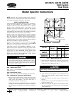
Step 1—Mount Unit to Pad
Refer to Fig. 1 for pad dimensions and dimensions needed to
mount unit to pad.
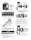
Step 2—Refrigerant Tubing
Refer to Fig. 2 for refrigerant tube dimensions and connections.
Step 3—Mechanical Connection (38YCP Model)
1. Remove plastic retainer holding outdoor piston and piston
retainer in the liquid service valve. Connect and tighten the
liquid service valve adapter to the valve body prior to
assembling ferrule/lock nut. (See Fig. 3.)
2. Cut tubing to the correct length, deburr and size as necessary,
making sure tube ends are square. If a large burr is evident, the
ID and OD must be deburred to allow the tube to bottom in
valve.
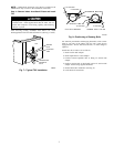
3. Remove lock nut and ferrule from plastic bag taped to service
panel. (See Fig. 4.) Remove the lock nut and ferrule from
liquid service valve adapter. (See Fig. 3.)
If undersized, damaged, or elliptically shaped tubing is used
when making connection, leaks could result.
4. Slide the lock nut and ferrule onto each tube. (See Fig. 5.)
5. Apply a few drops of refrigerant oil to the ferrule and valve
threads and adapter threads to reduce assembly torque and
assist sealing.
6. Insert tube end into the service valve or adapter until it
bottoms.
7. Push the ferrule into place and hand tighten the nut until an
increase in torque is felt.
8. Mark the nut and tube and tighten 1-1/2 turns from the mark.
(See Fig. 6.) Keep the tube bottomed in the valve and adapter
while tightening nut.
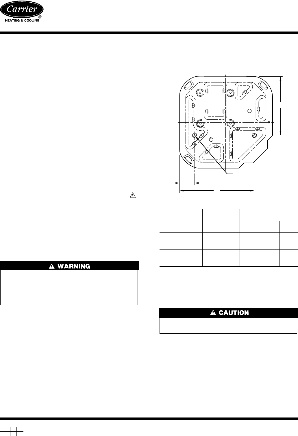
Fig. 1—Mount Unit to Pad
UNIT SIZE
MIN. PAD
DIM. (IN.)
TIEDOWN KNOCKOUT
LOCATIONS
A
(In.)
B
(In.)
C
(In.)
38YCB(P)018-030
38AYB018
38BYB018
22-1/2 X 22-1/2 3-11/16 18-1/8 14-3/8
38YCB(P)036-060
38AYB024-060
38BYB024-060
30 X 30 6-1/2 23-1/2 20
A94199
C
B
A
3
⁄
8
″D. (9.53) TIEDOWN
KNOCKOUTS (2) PLACES
Manufacturer reserves the right to discontinue, or change at any time, specifications or designs without notice and without incurring obligations.
Book 1 4
Tab 5a 5a
PC 101 Catalog No. 563-809 Printed in U.S.A. Form 38YCB-2SI Pg 1 6-96 Replaces: 38YCB-1SI