


6 720 608 034
Troubleshooting
19
6 Troubleshooting
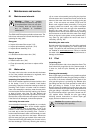
6.1 Introduction
Many of the questions customers ask regarding
operation of this unit can be answered by following the
troubleshooting steps as outlined below. Visit our web
site at www.boschpro.com for more detailed
troubleshooting. For best results, perform each step
before proceeding to the next. The suggested solutions
may require that the cover be taken off. (See chapter
3.4).
6.2 Pilot does not light
1. Verify gas supply is on at Natural Gas meter or
Propane Tank. Make sure all manual gas shut off valves
are in the open position. Have licensed gas technician
confirm adequate gas pressure at the inlet tap
(chapter 3.9). If gas is not present, verify manufacturer
supplied Maxitrol regulator is in the upright position. The
arrow on the back of the regulator should point in the
same direction as gas flow.
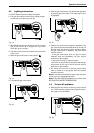
2. If the unit was just installed or the gas lines have been
worked on, there may be air in the gas line. Centered in
the sparking position, hold down the gas control slide
button while hitting the pilot igniter button every few
seconds. It may take several minutes to bleed air out of
the gas line.
3. Verify a spark is being thrown at pilot area while gas
control slide button, centered in the single flame
position, is being firmly depressed. Repeatedly push in
pilot igniter button to light the pilot. If no spark is
present, verify proper wire connection to the electrode.
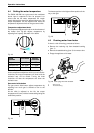
4. Pilot assembly may be blocked. Clean or replace the
pilot orifice (chapter 5.3).
6.3 Pilot lights, but goes out when
button is released
1. When lighting pilot ensure the gas control slide
button is fully depressed and held down for at least 20
seconds after pilot is lit.
2. Verify gas type indicated in rating sticker located on
right hand side of cover, coincides with the gas type you
are using. NG is a natural gas unit and LP is for liquid
propane.
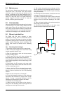
3. If using a power vent, check the safety spillage switch
reset button (the safety spillage switch is wired through
the water heater's thermocouple circuit). The spill
switch should be located at top of water heater close to
draft diverter (Consult manual that came with
powervent).
4. Check all connections of the pilot safety circuit. The
pilot safety circuit consists of a thermocouple, overheat
sensor (ECO), flue gas sensor, safety spillage
switch(models with Powervents only) and the
electromagnet (See parts diagram for locations). Clean
sensor connections with light sandpaper if corrosion is
evident. The electromagnet connection is 5mm nut from
the thermocouple which screws into a larger 17mm nut.
Tighten both nuts snugly but do not over tighten.
5. Pilot flame should be blue in color and completely
engulfing the tip of the thermocouple. If not, have a
licensed gas technician verify gas pressure is in
accordance with manufacturer's specifications
(chapter 3.9) and clean or replace the pilot orifice
(chapter 5.3).
6. Have a licensed gas technician verify the proper
operation of the thermocouple by measuring the
millivoltage from the thermocouple lead to ground. The
proper reading should be 24mVDC or greater. If the
reading is lower, the thermocouple may be defective.
Call Bosch Water Heating for further instructions.
6.4 Pilot goes out during or after hot
water use
1. Pilot outage during use typically results from the
unit's safety overheat/high limit sensors interrupting the
pilot circuit. The GWH 425 PN does not have a
thermostat. If inlet water is preheated, the unit will
overheat, stopping the flow of gas. Plumb inlet with a
cold water line only.
2. Failure to vent properly by reducing pipe diameter,
improper use of elbows or not meeting required vent
length are common causes that deactivate the pilot
safety circuit. Confirm venting is in accordance with
manufacturer's specifications (see chapter 3.7).
3. Confirm the combustion air requirements are being
met in accordance with manufacturer's specifications
(see chapter 3.6). Proper venting and combustion air
will ensure a proper draft.
4. Confirm that the burners in the water heater go off
immediately when the hot water is turned off. If they
remain on or shut down slowly, then the overheat
sensor (ECO) will interrupt the pilot circuit and shut off
all gas to the heater. The water valve assembly, which
actuates the burners, may be dirty and require periodic
maintenance (every 2 - 5 years depending on water
quality and use) (see chapter 5.2).
5. Check all connections of the pilot safety circuit. The
pilot safety circuit consists of a thermocouple, overheat
sensor (ECO), flue gas sensor, safety spillage
switch(models with Powervents only) and the
electromagnet (See parts diagram for locations). Clean
sensor connections with light sandpaper if corrosion is
evident. The electromagnet connection is 5mm nut
from the thermocouple which screws into a larger
17mm nut. Tighten both nuts snugly but do not over
tighten.