


Applications manual | 11.2007Bosch Water Heating
Applications manual
| 7
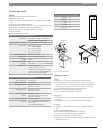
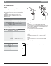
2.3 Bosch GWH C 800 ES
Features:
Electronic ignition and built in power vent
Condensing technology with 92% thermal effi ciency
Vents vertically or horizontally with 3" or 4" PVC, CPVC or ABS
(Schedule 40) vent pipe.
Direct vent room-sealed combustion with concentric venting
option
Computerized temperature control — ensures temperature stability
Model GWH C 800 ES N for natural gas (NG) supply
Model GWH C 800 ES L for liquid propane (LP) supply
15-year warranty
Qualifi es for $300 tax credit
GWH C 800 ES Technical Specifi cations
Gas input Natural Gas: 19,900 - 199,000 BTU
LP Gas: 19,900 - 199,000 BTU
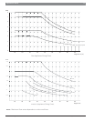
Minimum fl ow to activate 0.65 gallons per minute (gpm)
Flow rates 45˚F rise @ 8.0 gpm
55˚F rise @ 6.4 gpm
65˚F rise @ 5.5 gpm
77˚F rise @ 4.6 gpm
90˚F rise @ 3.9 gpm
Thermal Effi ciency NG: 92% LP: 92%
Dimensions 30½" h x 17⅞" w x 11¼" d
Weight 74 lbs.
Modulating gas valve yes
Ignition Electronic
Accessories Outdoor kit (PTOK)
Wireless Remote (TSTAT2)
Tankless Link Cascading Kit (TLINK)
Freeze Prevention Kit (8700400022)
Water Filter Kit (8703305356)
Concentic Termination Kit
(BWH60L46)
GWH C 800 ES Installation Specifi cations
Gas connection ¾" Male NPT
Water connections ¾" Male NPT
NG gas pressure Minimum: 4" W.C.
Maximum: 14" W.C.
LP gas pressure Minimum: 9" W.C.
Maximum: 14" W.C.
Water pressure
(Static)
Minimum: 30 PSI
Minimum well pressure: 40 PSI
Maximum: 150 PSI
Electrical supply 120VAC - plugs in
Venting 3" or 4" PVC, CPVC, or ABS
(Schedule 40) direct vent sealed
combustion
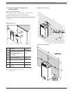
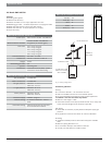
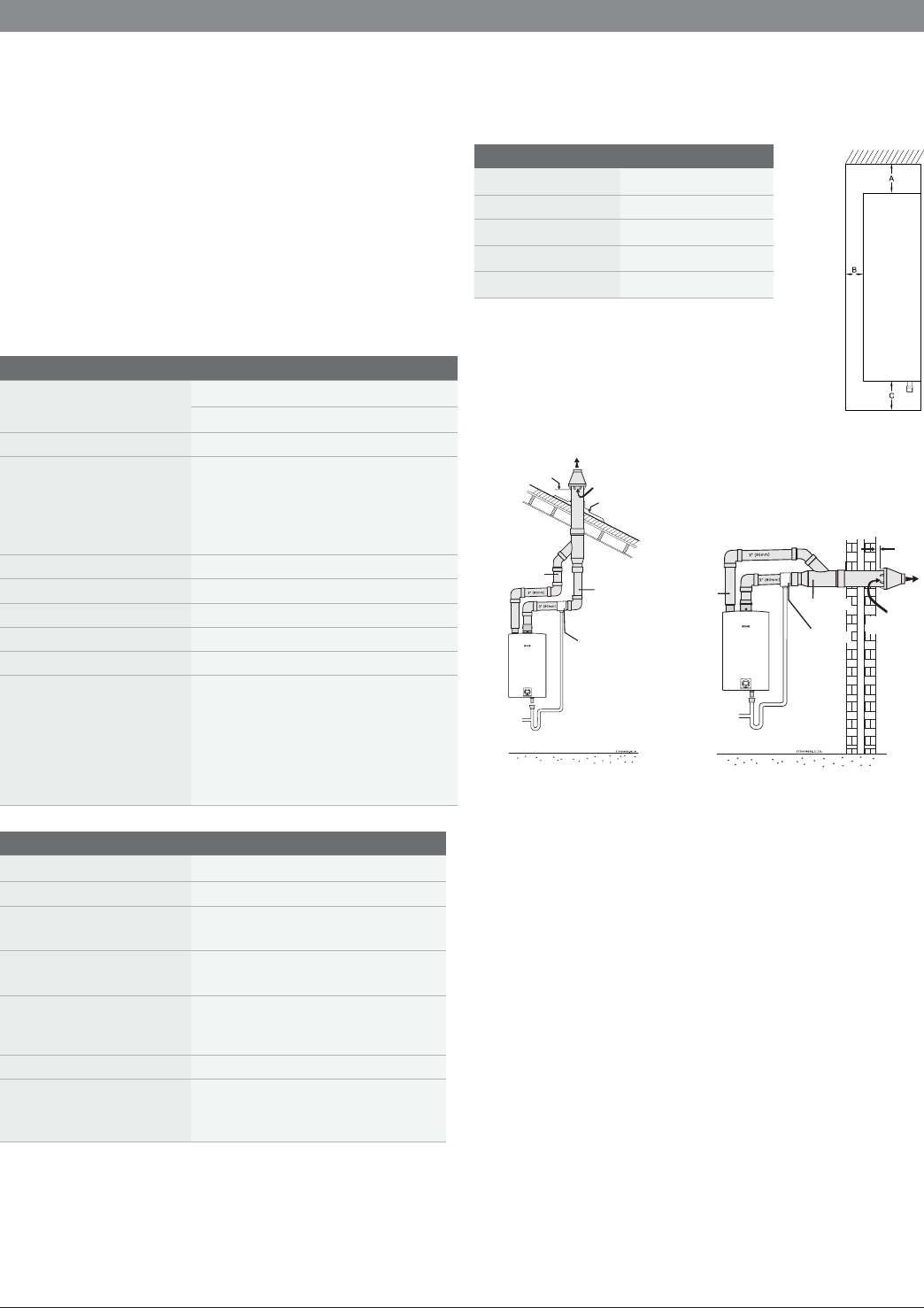
GWH C 800 ES Installation Clearances
Top (A) 12"
Front (B) 1"
Back 0"
Sides 1"
Floor (C) 12"
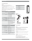
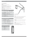
INTAKE
EXHAUST
COMBUSTION
AIR
MAINTAIN 12 IN.
(1
8 IN. FOR CANADA)
MINIMUM CLEARANCE
ABOVE
HIGHEST ANTICIPATED
SNOW LEVEL.
MAXIMUM OF 24 IN.
ABOVE ROOF.
VENT
ROOF BOOT/
FLASHING (FIELD
SUPPLIED
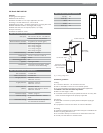
DRAIN TEE
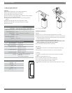
INTAKE
EXHAUST
MINIMUM
1”
VENT
COMBUSTION
AIR
DRAIN TEE
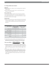
Fig. 1 Venting confi gurations
Installation guidelines:
Venting:
Must be 3" or 4" PVC, CPVC or ABS (Schedule 40) vent pipe.
Attach drain for internal condensate siphon and dispose of
according to local codes.
Do not combination vent with any other appliance.
Install an external condensate drain where applicable.
See manual for vent terminator clearances.
Gas piping:
Heater will not function properly without adequate supply gas
pressure.
Any appliance connector should be ¾" minimum diameter
Plumbing:
Install the included pressure relief valve and pipe to suitable
drain.
Minimum piping diameter is ¾".
Do not solder directly to the bottom of the unit.
Use unions to facilitate easy future maintenance.
Use full port ball valves for isolation valves.
Partially fi ll condensate drain tube loop (where applicable)