


116 720 607 026
OPERATING INSTRUCTIONS
Before proceeding with the operation of the heater make
sure that the system is filled with water.
Open the cold water inlet supply to the heater fully.
Open a hot water faucet to permit the water to fill the heater
and the piping and to eliminate the air trapped in the system
Close the hot water faucet after the water flows freely and
all the air has escaped from the system. The water heater is
now ready to operate.
FOR YOUR SAFETY READ BEFORE
OPERATING YOUR HOT WATER HEATER
Warning: If you do not follow these instructions exactly,
a fire or explosion may result causing property damage,
personal injury or loss of life.
A. This appliance is equipped with electronic ignition for
lighting the pilot and main burners. When turning the heater
on, follow these instructions exactly.
B. Before operating the unit, set the On/Off switch to the
On ( ) position. The On/Off switch is located behind
the flip-down coverplate on the front panel strip. Smell all
around the appliance area for gas. Be sure to smell next to
the floor because some gas is heavier than air and will settle
on the floor.
WHAT TO DO IF YOU SMELL GAS
- Do not try to light any appliance.
- Do not touch any electric switch; do not use any phone
in your building
- Immediately call your gas supplier from a neighbor’s
phone. Follow the gas supplier’s instructions.
- If you cannot reach your gas supplier, call the fire
department.
C. Use only your hand to push in the on/off control button.
Never use tools. Follow these instructions exactly. If control
button is jammed, close the gas supply and call a qualified
service technician. Attempted forceful repair may result in a
fire or explosion.
D. Do not use this appliance if any part has been under
water. Immediately call a qualified service technician to
inspect the appliance and to replace any part of the control
system and any gas control which has been under water.
WATER CONNECTIONS
Install the heater centrally in the building if possible and
make hot water piping runs as short as possible When facing
the heater, the cold water inlet will be on the right and the
hot water outlet on the left.
Although water piping throughout the building may be other
than copper, copper or galvanized piping should be used
when connecting to the heaters ½” male NPT flex connectors
(follow local codes if more stringent). Plastics or other PEX
type plumbing line materials are not suitable for connecting
directly to the water heater. Keep water inlet pipe to no less
than ½” (19.05mm) diameter to allow the full flow capacity.
If the cold and hot connections to the heater are reversed,
the heater will not function.
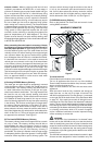
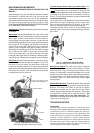
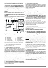
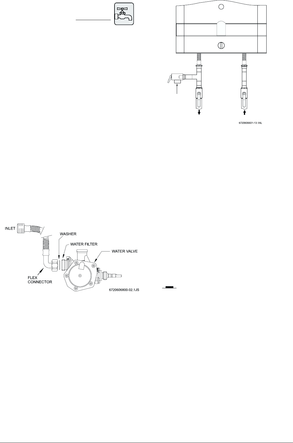
The 425 HN is provided with one flexible type connector
that must be connected to the cold inlet fitting of the water
valve as shown in Fig. 6. The union end of the flexible
connector should be attached to the rear inlet port of the
water valve with the supplied washer gasket. No pipe dope
or thread tape is to be used at this joint. The ½” flexible hot
water outlet line is supplied attached to the heater.
Be certain there are no loose particles or dirt in the piping.
Blow out or flush the lines before connecting to the water
heater. Full port valves should be installed on both the cold
water supply and hot water outlet lines to facilitate servicing
the heater (see Fig. 7). For installation on a private well
system with the use of a pressure tank, the lowest pressure
range setting recommended is 30-50 psi (2.07-3.45 bar).
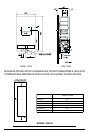
Fig. 6 - Water valve - top view
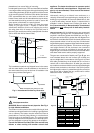
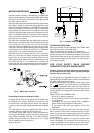
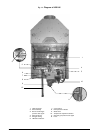
Connecting the pressure relief valve (PRV)
A listed pressure relief valve supplied with the heater must
be installed at the time of installation. No valve is to be
placed between the PRV and the heater. No reducing
coupling or other restriction may be installed in the discharge
line.
The discharge line must be installed such that it allows
complete drainage of both the PRV and the line.
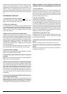
The location of the PRV must be readily accessible for
servicing or replacement, and be mounted as close to the
water heater as possible. See Fig 7. To install the PRV, a
suitable fitting connected to an extension on a “T” fitting
can be sweated to the hot water line.
Support all piping.
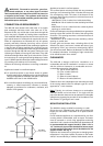
Fig. 7 - Pressure Relief Valve
Pipe to
appropriate
discharge
Hot Cold