


136 720 607 017
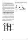
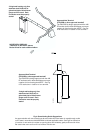
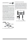
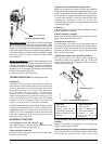
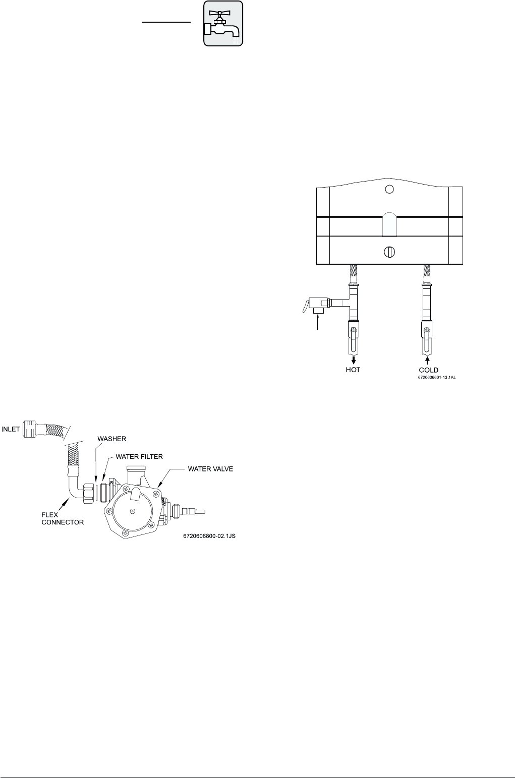
Fig.7 - Water valve and water connectors, top view
WATER CONNECTIONS
Install the heater centrally in the building if possible and
make hot water piping runs as short as possible When facing
the heater, the cold water inlet will be on the right and the
hot water outlet on the left..
Although water piping throughout the building may be other
than copper, copper or galvanized piping should be used
when connecting to the heaters ½” male NPT flex connectors
(follow local codes if more stringent). Plastics or other PEX
type plumbing line materials are not suitable for connecting
directly to the water heater. Keep water inlet pipe to no less
than ½” (19.05mm) diameter to allow the full flow capacity.
If the cold and hot connections to the heater are reversed,
the heater will not function.
The 425 EF is provided with one flexible type connector
that must be connected to the cold inlet fitting of the water
valve as shown in Fig. 7. The union end of the flexible
connector should be attached to the rear inlet port of the
water valve with the supplied washer gasket. No pipe dope
or thread tape is to be used at this joint. The ½” flexible hot
water outlet line is supplied attached to the heater.
Be certain there are no loose particles or dirt in the piping.
Blow out or flush the lines before connecting to the water
heater. Full port valves should be installed on both the cold
water supply and hot water outlet lines to facilitate servicing
the heater (see Fig. 7). For installation on a private well
system with the use of a pressure tank, the lowest pressure
range setting recommended is 30-50 psi (2.07-3.45 bar).
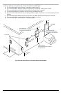
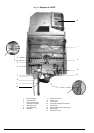
Connecting the pressure relief valve (PRV)
The listed pressure relief valve supplied with the heater must
be installed at the time of installation. Should a discharge
line be added to the PRV no valve is to be placed between
the PRV and the heater. No reducing coupling or other
restriction may be installed in the discharge line. The
discharge line must be installed such that it allows complete
drainage of both the PRV and the line. The location of the
PRV must be readily accessible for servicing or replacement
and be mounted as close to the water heater as possible. To
install the PRV, a suitable fitting connected to an extension
on a “T” fitting can be sweated to the hot water line. See
Fig 8.
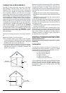
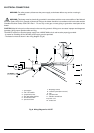
Fig. 8 - Plumbing and Pressure Relief Valve
PIPE PRV TO
APPROPRIATE
DISCHARGE