


116 720 607 017
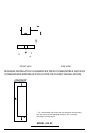
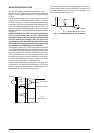
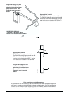
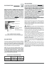
Fig. 6 - Appliance pressure regulator
(with directional arrow on reverse side pointing up)
GAS LINE SIZING
The pressure regulator provided with the heater is adjusted
to deliver the proper gas pressure (as indicated on the rating
plate and in the manual for altitude up to 2000 feet (660
meters) above sea level. On appliances being installed above
2000 ft (660 meters) elevation, the inlet gas pressure should
be set at installation to the value shown below.
NOTE: The gas pressures specified below refer to
pressures taken at the pressure tap on the gas inlet pipe
just above the regulator (See Fig 6). These readings
should be taken while the heater is operating at full input
— i.e. maximum water flow with the temperature dial
selector turned all the way clockwise.
Above 4.500 ft consult your local gas provider.
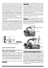
GAS CONNECTIONS
NOTE: The 425 EF is supplied with a gas pressure
regulator that must be installed on the heater before
attaching the gas supply line. See figure 6. Failure to
install the gas regulator as shown in figure 6 will be a
violation of CSA certification of the unit. The regulator
supplied with the heater is preset for the gas shown on
the rating plate to the correct pressure. It is an appliance
level regulator designed for (low inlet) pressure (less
than 1/2 Psig or 15” W.C.) DO NOT connect to an
unregulated or high pressure propane line or to a high
pressure commercial natural gas line.
GAS LINE SIZING
-It is strongly recommended that the Natural Gas pipe
be Black Iron pipe the entire distance from the outside
meter to the inlet of the 425 EF regulator. 1/2” Black Iron
pipe up to 10 feet, 3/4” Black Iron pipe up to 40 feet and
1” Black Iron pipe up to 125 feet distances. Flex line tubing
is NOT recommended, but if used then oversize it.
-It is strongly recommended that the LP Gas pipe be
semi-rigid copper or Black Iron pipe from the outside
regulator to the inlet of the 425 EF regulator. For semi-
rigid copper piping: 5/8” up to 20 feet and 3/4” up to 50
feet distances. For Black Iron piping: 1/2 “ up to 30 feet
and 3/4” up to 150 feet distances. Flex line tubing is NOT
recommended, but if used then oversize it.
THESE FIGURES ARE FOR 425 EF SUPPLY ONLY, ALL
OTHER APPLIANCES IN THE BUILDING WILL NEED TO
BE INCLUDED IN THE PIPE SIZING.
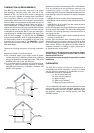
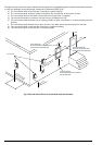
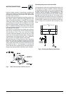
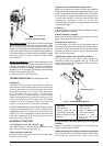
National Fuel Gas Code requires that a sediment trap (drip
leg) be installed on gas appliances not so equipped. The
drip leg must be accessible and not subject to freezing
conditions. Install in accordance with the recommendations
of the serving gas supplier.
WARNING: The heater must be disconnected from
the gas supply piping system during any pressure testing of
that system at test pressures in excess of .5 psig.
The water heater must be isolated from the gas supply piping
system by closing the manual shutoff valve during any
pressure testing of the gas supply piping system at test
pressures equal to or greater than .5 psig.
The water heater, including the pressure regulator provided
with it, must not be operated at gas supply pressures in
excess of .5 psig. If overpressure has occurred, such as
through improper testing of the gas lines or malfunction of
the supply system, the gas valve and regulator must be
checked for safe operation.
When your connections are made, check for gas leaks at
all joints (not just the ones you made). Apply some soapy
water to all gas fittings and gas valve. Soap bubbles are a
sign of a leak.
NOTE: Do not apply soap solution to pilot filter screen or
pilot orifice area. If you have a leak, shut off the gas. After
verifying that required gaskets are in place, tighten
appropriate fittings to stop leak. Turn the gas on and check
again with a soapy solution. Never test for gas leaks using
a match or flame.
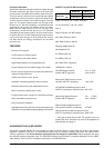
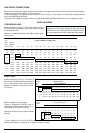
Altitude Natural Gas Liquid Propane
inches W.C: inches W.C:
0' - 2.000 ft 5.38 9.9
2.000 ft - 4.500 ft 4.40 7.90
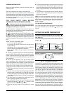
GAS INLET PIPE
PRESSURE TAP
APPLIANCE PRESSURE
REGULATOR
(with directional arrow on
reverse side pointing upward)
PLASTIC CAP
MAXIMUM INLET PRESSURE SETTINGS