


6 720 608 782
8
Installation instructions
3 Installation instructions
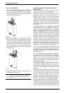
3.1 Tools required for installation
• Philips head screwdriver
• Flat head screwdriver
• Adjustable wrench
• Level
• Thermometer
• Standard plumbing tools
•Manometer
• Drill
• Pipe wrench
• Adjustable pliers
• Pipe fitting tools
• Hacksaw with metal blades
•Hole saw.
3.2 Introduction
Please follow these instructions. Failure to follow
instructions may result in:
B Damage or injury.
B Improper operation.
B Loss of warranty.
If you are unable to perform the tasks required to install
this heater properly, please contact a locally licensed
plumber or gas technician.
Common installation practice is to determine the
venting/intake system layout and penetration and then
work back to the heater.
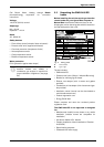
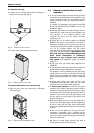
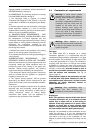
3.3 Venting
3.3.1 Vent material and specifications
Establish vent clearances that comply with the vent
manufacturer's specifications. In all cases, follow local
codes. See Table 2.
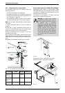
The appliance should be located as close to the point
of vent termination as possible. The maximum vent
length is 26 feet (8 m) with one 90 degree elbow and
approved terminator. Subtract 2.5 feet from the total
vent length for each additional 90° elbow used (a
maximum of three 90° elbows are permitted in the
total exhaust vent length), or subtract 1.25 feet for every
45° elbow used. Horizontal sections of vent must pitch
Warning: Do not reduce the vent
(exhaust and combustion) pipe sizes
and do not common vent with any other
vented appliance or stove.
Warning: Failure to vent the exhaust
gases to the outside with sealed
stainless steel vent pipe (AL29-4C)
may result in dangerous flue gases
filling the structure in which it is
installed.
Warning: Do not mix vent pipe or
joining methods from different
manufacturers.
Warning: Proper end terminal / rain
cap must be used. Failure to do so may
result in damage to the appliance.
This damage is not covered under
the manufacturer's warranty.
Caution: The vent system must be
installed by a qualified installer in
accordance with these instructions. If
improperly installed, a hazardous
condition such as explosion or carbon
monoxide poisoning could result.
Bosch Water Heating will not be
responsible for improperly installed
appliances.
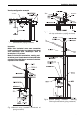
Warning: In areas where outside
temperatures routinely come close to
freezing, sealed combustion operation
is required. Use a concentric
termination or separate terminations for
combustion and vent, which must be
installed on the same wall or roof
surface, however never facing the
direction of prevailing winds. Failure to
do so may result in heat exchanger
freezing up and bursting. This failure is
not covered under the manufacturer's
warranty.
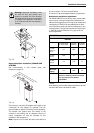
Diam. Min.
lenght
Max.
length
Material
Exhaust
Vent
3 or 4
inches
3 feet 26 feet with
1 90° elbow
and terminal
Sealed single wall
stainless steel
(AL29-4C)
Intake
Vent
3 or 4
inches
1 90°
elbow
26 feet with
1 90°elbow
and terminal
Sealed PVC or
any other rigid
pipe
Table 2 Venting Specifications