


6 720 606 518
Installation instructions
13
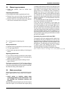
3.8 Measuring gas pressure
B Proper gas pressure must be verified upon
installation.
Connecting manometer
B Shut off gas with installer supplied shutoff valve.
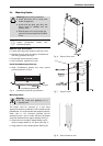
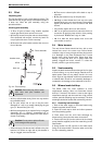
B Remove front cover and locate inlet gas pressure
measuring tap above the regulator, see Fig. 15.
B Remove screw from test point above the regulator
and connect manometer tube on test point.
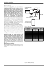
Fig. 15 Gas pressure measuring point
A Inlet tap
Static pressure test
B Operate all other gas appliances at maximum output.
B Turn gas supply back on.
B Record static gas pressure reading on back page of
manual.
Operating pressure test
B Turn on all hot water taps served by the water heater.
B Operate all other gas appliances on same gas piping
system at maximum output.
B Record operating gas pressure reading on back
page of manual.
Gas pressures lower than 5.7" W.C. for Natural Gas or
10.5" W.C. for LP Gas will result in insufficient degree
rise to the hot water being used, and must be corrected.
See Gas Line Sizing under chapter 3.7.
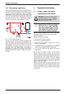
3.9 Water connections
When facing the heater, the ½” cold water inlet is on the
bottom right and the hot water outlet is on the bottom
left.
B Install unions or isolation valves when
connecting plumbing to the water heater. This
will facilitate any necessary cleaning and
servicing.
Although water piping throughout your structure may be
other than copper, we recommend that copper piping
or suitably rated stainless steel flex line piping be used
for at least three feet before and after the heater (follow
local codes if more stringent). Never sweat any rigid
piping directly to or beneath the water connections or
damage can occur to the internal water valve from
heating of the pipe. Plastics or other PEX type plumbing
line materials are not recommended for connecting
directly to the water heater. Keep water inlet and outlet
pipes to no less than ½" (12.7mm) diameter to allow the
full flow capacity.
It is recommended that all water piping after the heater
be properly insulated to avoid heat loss.
If the cold and hot connections to the heater are
reversed, the heater will not function. Be certain there
are no loose particles or dirt in the piping. Blow out or
flush the lines before connecting to the water heater.
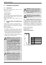
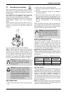
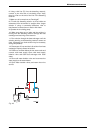
Full port shutoff valves should be installed on both the
cold water supply and hot water outlet lines to facilitate
servicing the heater (see Fig. 16). For installation on a
private well system with the use of a pressure tank, the
lowest pressure range setting recommended is 30-50
psi (2.07 and 3.45bar).
Connecting the pressure relief valve (PRV)
The pressure relief valve supplied with the heater must
be installed at the time of installation. No valve is to be
placed between the PRV and the heater. No reducing
coupling or other restriction may be installed in the
discharge line. The discharge line must be a minimum of
4” above a drain and installed such that it allows
complete drainage of both the PRV and the line.
The loci0.005 lionf1( the PRe muss)5.4beis redilmayei
servic6-3.2(v)-0.5(g oe )-6(se)9.[(plaommt(i)5.,oe )-V anbeimoumt(i)5.(lease )6.oe