


6 720 607 072
32
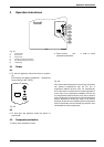
Special adjustment for measuring and adjusting CO2 levels
9 Special adjustment for measuring and adjusting CO
2
levels
The CO
2
can only be adjusted by a certified gas
technician with a calibrated CO
2
analyzer.
Static Gas Pressure: “ WC
P1 Operating Pressure: “ WC
The P1 minimum operating pressure is 5" WC for
Natural Gas and 11"WC for Propane. Do not proceed
in adjusting CO
2
until pressure has been verified to be
at or above these levels, but not to exceed 14” WC.
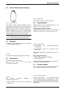
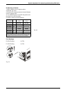
A. Once Pressure is good
B Turn ON/OFF switch to the OFF (O) position.
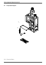
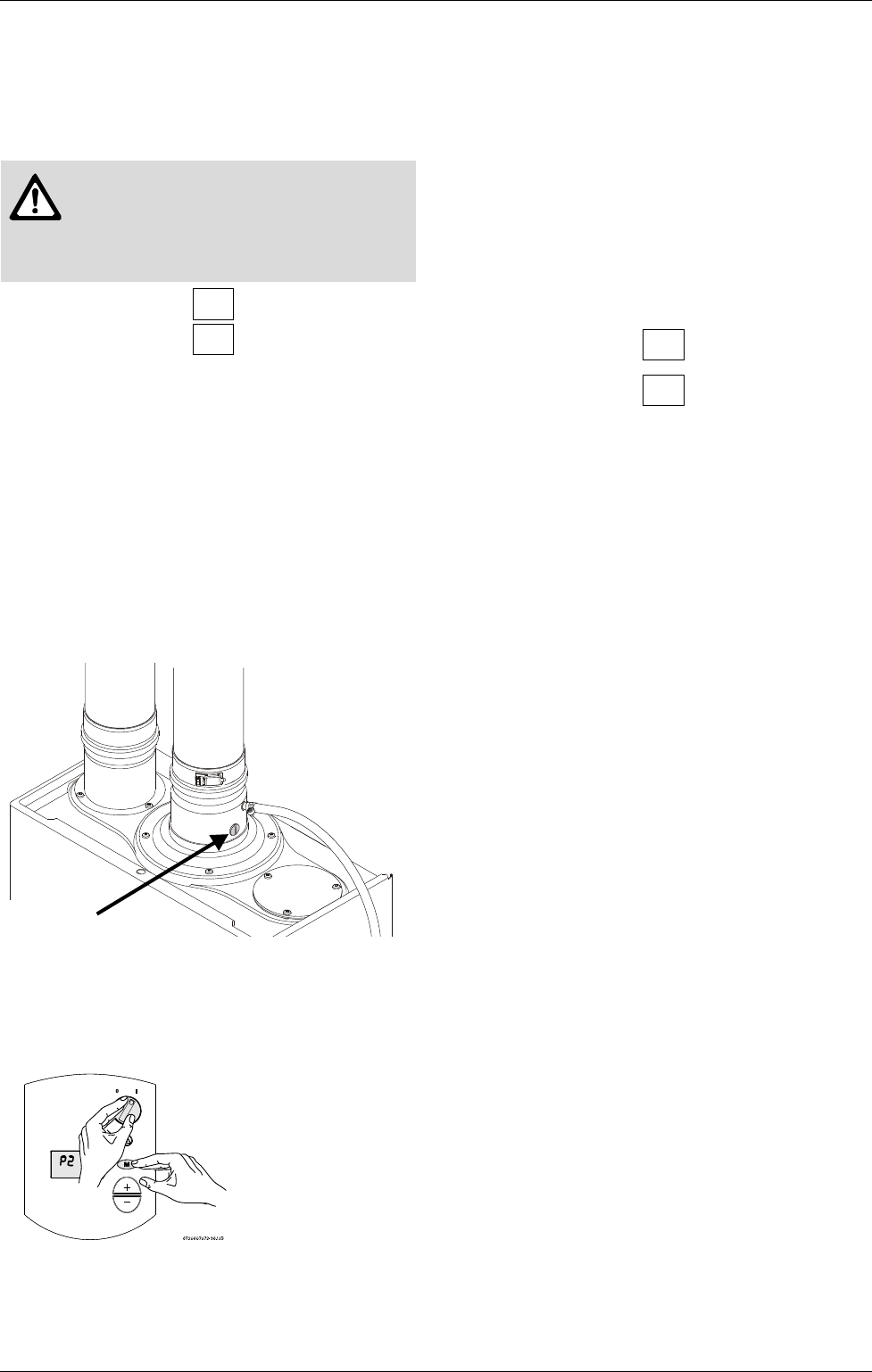
B Remove brass flat head screw on the exhaust collar
as seen in Fig. 42.
B Insert CO
2
analyzer probe into the measuring port.
The tip of the probe should be in the center of the flue
pipe (approx 1.5" inserted).
Fig. 42
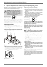
B While holding the Program (M) button, move the ON/
OFF switch to ON (I) position (see Fig. 43). As soon
as ‘188’ flashes on the display, release the Program
button. The display should now read P2.
Fig. 43
B. Measuring CO
2
(Cover Installed):
B Open hot water taps to achieve a flow rate of at least
4 gallons per minute. (1 tub and 2 sinks should be
sufficient).
B Record the CO
2
reading in P2 below. (Analyzer
reading may take several minutes to stabilize).
B Press the ‘+’ button until P1 appears. Unit will ramp
up to high fire and the flow should increase.
B Record the CO
2
reading in P1 below.
P2 CO
2
Reading: % CO
2
P1 CO
2
Reading: % CO
2
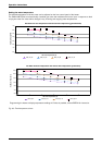
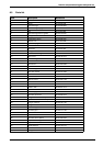
Compare your readings to those found in table 9 under
the “With Front Cover” column. If CO
2
readings are off
make adjustments as outlined below.
Note: The “Without Front Cover” column give
approximate values with the cover off to ease the
adjustment process. Final readings should be taken
with the cover on.
C. Adjusting CO
2
:
Note: P1 adjustment will change the P2 reading.
Confirm the P1 value BEFORE adjusting the P2 level.
1. P1 CO
2
level off:
B Loosen yellow painted Philips screw (1) and cover
should rotate down (2) revealing a brass slotted
screw. Fig. 44.
B Adjusting the slotted screw counter clockwise will
raise P1 CO
2
levels and clockwise will lower P1
CO
2
levels. Adjustments to the slotted screw will
also change P2 CO
2
levels.
2. P2 CO
2
level off:
B Remove yellow painted #40 Torx cover from the front
of the gas valve. (Fig. 45) A plastic #40 Torx screw
will be revealed.
B Adjusting the plastic #40 Torx screw counter
clockwise will lower P2 CO
2
levels and clockwise
will raise P2 CO
2
levels.
Note: These screw adjustment are very sensitive and
may take several minutes to stabilize.
3. Verify both P1 and P2 are within the ranges specified
in table 1 under the “With Front Cover” column. Repeat
steps 1 and 2 as necesssary until CO
2
values are within
the specified ranges.
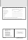
Caution: One factor that may affect
CO
2
levels is improper gas pressure.
Please see Chapter 2.12 for the
procedure to measure gas pressure
and record your findings below: