


6 720 607 072
18
Appliance details
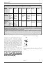
HIGH ALTITUDE OPERATION
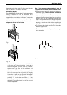
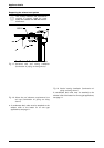
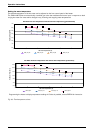
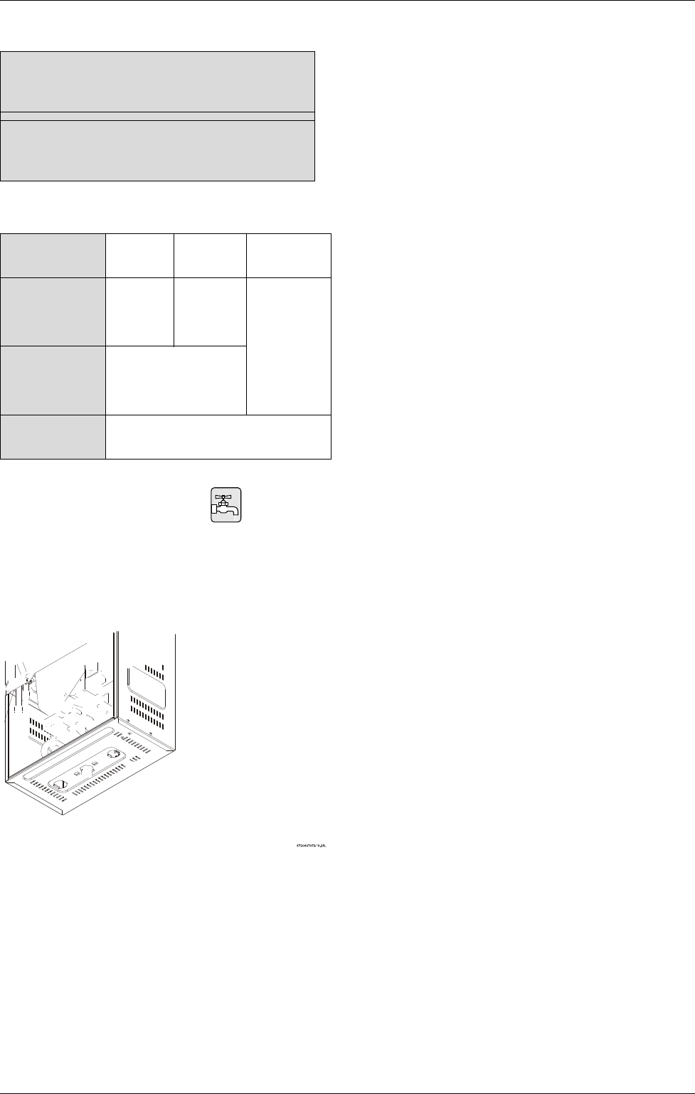
2.13 Water connections
When facing the heater, the ¾” cold water inlet is on the
bottom right and the hot water outlet is on the bottom
left. Install the heater centrally in the building if possible
and make hot water piping runs as short as possible.
Fig. 25
B THE USE OF A UNION WHEN CONNECTING
BOTH WATER PIPES TO THE INLET AND
OUTLET CONNECTIONS IS RECOMMENDED,
THIS WILL FACILITATE ANY NECESSARY
SERVICING AND REQUIRED CLEANING OF
THE INLET WATER PARTICLE SCREEN.
Although water piping throughout the building may be
other than copper, we recommend that copper,
galvanized or suitably rated stainless steel flex line
piping be used for the water heater connections (follow
local codes if more stringent). Never sweat any rigid
piping directly to or beneath the water connections,
damage can occur to the internal water valve from
heating of the pipe. Plastics or other PEX type plumbing
line materials are not suitable for connecting directly to
the water heater. Keep water inlet and outlet pipes to no
less than ¾" (19.05mm) diameter to allow the full flow
capacity.
If the cold and hot connections to the heater are
reversed, the heater will not function. Be certain there
are no loose particles or dirt in the piping. Blow out or
flush the lines before connecting to the water heater.
Full port valves should be installed on both the cold
water supply and hot water outlet lines to facilitate
servicing the heater (see Fig. 26). For installation on a
private well system with the use of a pressure tank, the
lowest pressure range setting recommended is 30-50
psi (2.07 and 3.45bar).
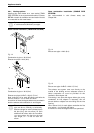
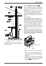
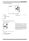
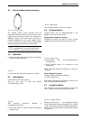
Connecting the pressure relief valve (PRV)
A listed pressure relief valve supplied with the heater
must be installed at the time of installation. No valve is
to be placed between the PRV and the heater. No
reducing coupling or other restriction may be installed
in the discharge line. The discharge line must be a
minimum of 4” above a drain and installed such that it
allows complete drainage of both the PRV and the line.
The location of the PRV must be readily accessible for
servicing or replacement, and be mounted as close to
the water heater as possible. See Fig. 26. To install the
PRV, a suitable fitting connected to an extension on a
“T” fitting can be sweated to the hot water line.
Support all piping.
Fig. 26 Plumbing Connections and Pressure Relief
Valve
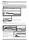
Static Gas Pressure Reading (see Chapter 2.12)
enter here: ___________________
Operating Gas Pressure Reading (see Chapter 2.12)
enter here: ___________________
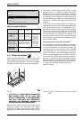
Table 5
Altitude Natural
Gas:
Liquid
Propane:
0 - 4,000 ft
(0 - 1,219 m)
no
modification
no
modification
For operation at
elevations
above 2,000 ft
(610 m) the
equipment
ratings shall be
reduced at the
rate of 4% for
each 1,000 ft
(305 m) above
sea level
4,000 ft - 7,000 ft
(1,219 m - 2,134 m)
CO
2
adjustment with flue
gas analyzer required See
chapter
9
for instructions.
Above 7,000 ft
(above 2,134 m)
Not approved
Table 6