


6 720 607 072
Appliance details
11
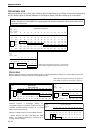
Note: reduce 2½ ft for each 90° elbow used after the
first one, reduce 1 ¼ ft for each 45° elbow.
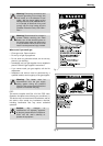
Vent Safety System
The GWH-635-ES will shut down if inadequate exhaust
venting is detected or a lack of combustion air is
provided to the unit; see troubleshooting section on
page 24. See error code to confirm error, correct the
problem and then reset the heater before operating.
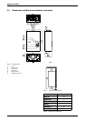
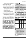
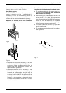
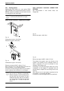
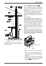
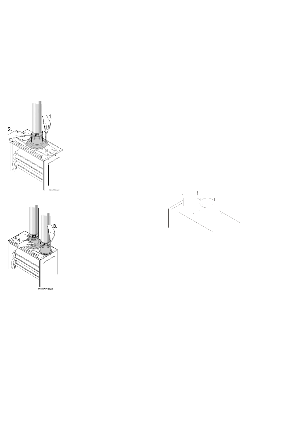
Attaching the exhaust and air inlet connection
adaptors to the top of the heater
Fig. 9
Fig. 10
B Attach the flue gas exhaust accessory (8 705 504
114) to the top of the unit (position 1) using the 4
screws and gasket provided, and fully insert 3"
stainless steel vent pipe into the accessory and
tighten the clamp (position 2).
B Attach the combustion air inlet accessory (8 705
504 115) to the top of the unit (position 3) using the
3 screws and gasket provided, and fully insert 3"
combustion air pipe into the accessory and tighten
the clamp (position 4). NOTE: The appliance has the
possibility to mount the combustion air inlet
accessory on the top right or on the top left side of
the heater. The combustion air inlet that is not used
must be kept sealed.
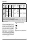
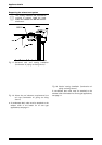
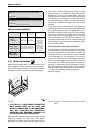
Use of the external condensate drain tube kit
(supplied with the heater) on the exhaust collar
B The condensate drain tube kit must be used for all
installation types. Failure to install condensate
drain will void the warranty.
B When installing the condensate drain tube kit at the
exhaust collar (see diagram below), be sure to form a
trap by means of a 3" (76.2 mm) loop filled with
water. The supplied tube is 3/8" ID high temperature
silicone and must be attached to the condensate
tapping on the exhaust collar with its supplied gear
clamp (first remove screw at tapping point).
B To increase tube length, connect vinyl type tubing
after the supplied tube.
B The condensate must be disposed of according to
local regulations.
Fig. 11