


9
Installation Instructions
Gas Connection
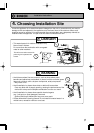
1) Fit a union to the water heater gas inlet for easy connec-
tion and removal. The thread diameter is 20 mm.
THIS DOES NOT INDICATE THE SIZE OF THE GAS
SUPPLY.
2) Fit an AGA / NZGA approved isolating gas cock in the
supply line adjacent to the water heater gas connection.
3) Ensure that the supply pipe and the gas pressure regula-
tor (LPG or Natural Gas) has sufficient flow capacity for
this and other appliances connected to the fitting line.
4) For LPG appliances ensure that gas cylinders are of suf-
ficient size. The water heater alone will require 2 x 45 Kg
capacity cylinders.
5) Before connecting the appliance to the gas service,
purge any debris or air from the gas service.
6) Check all joints for leaks with an approved leak tester
after connection.
Follow the instructions from the gas supplier.
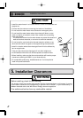
Gas Pressure
Size the gas line according to total MJ/h
demand of the building and length from
the meter or regulator so that the follow-
ing supply pressures are available even
at maximum demand refer AS5601:
Natural Gas Supply Pressure
Min. 1.13 kPa
Max. 3.00 kPa
LP Gas Supply Pressure
Min. 2.75 kPa
Max. 3.50 kPa
7.
Gas Piping
The appliance must be disconnected from the gas supply piping system during any pressure testing of
that system at test pressures in excess of 3.5 kPa.
The appliance and its gas connections must be leak tested before placing the appliance in operation.
The inlet gas pressure must be within the range specified. This is for the purposes of input adjustment.
In order to choose the proper size for the gas line, consult local codes and / or the AS5601.
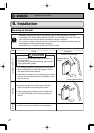
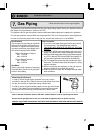
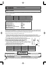
Measuring Gas Pressure
In order to check the gas supply pressure to the unit, a tap is
provided on the gas inlet. Remove the hex head philips screw from
the tap, and connect a manometer using a silicon tube.
In order to check the gas manifold pressure on the gas valve inside
the unit. The pressure can be checked by removing the hex head
philips screw and connecting a manometer with a silicon tube.
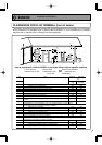
Gas Meter
Select a gas meter capable of supplying
the entire MJ/h demand of all gas appli-
ances in the building.
Ensure that the gas pipe size is correct. If undersized the appliance will not operate correctly
SERVICE CALLS ARE CHARGEABLE FOR UNITS WITH INCORRECT PIPE SIZES OR BLOCKED GAS OR
WATER FILTERS.
Refer to AS 5601 Installation Code or NZS 5261 : 2003 installation code for pipe sizing and details.