


• Pele el aislamiento del cable de toma de tierra, aproximadamente 1,9 cm. El hilo de toma de tierra
debe conectarse al terminal de poste con la marca "GR".
• Asegúrese de que los tornillos de los bloques de terminales están firmemente apretados. Las
conexiones sueltas pueden provocar el calentamiento de los cables.
• Asegúrese de que el cable de toma de tierra está enrollado en el vástago del terminal y en la
arandela de asiento. La tuerca debe apretarse firmemente.
• Coloque la cubierta delantera y apriete los tornillos de fijación.
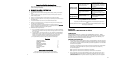
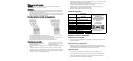
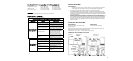
Piezas de recambio
Nº de pieza
Descripción
(Consulte el Diagrama 1,
Página 3)
93 793770
Bloque terminales 4 salidas
(AE115)
93 793771
Bloque terminales 6 salidas
(AE125)
93 793772
Tapa frontal (blanca)
93 793773
Disyuntor térmico
93 793774
Transductor de flujo
93 793775
Caja de PCI (tapa)
93 793776
Caja de PCI (base)
93 793777
PCI de control (AE115)
93 793778
PCI de control (AE125)
93 793779
Pomo de ajuste
93 793784
Filtro de entrada _”
Para obtener información
adicionales, consulte con su
distribuidor local.
SI TIENE ALGUNA PREGUNTA
SOBRE MANTENIMIENTO O
INSTALACIÓN, LLAME AL
TELÉFONO
866-330-2729
Fax: 802-496-6924
www.boschhotwater.com
Empezar a utilizar el PowerStar
Comprobación de pérdidas
• Deje circular el agua por la unidad durante unos segundos. Compruebe que no haya pérdidas en
las juntas de las tuberías.
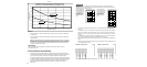
Ajuste del disco de temperatura
• El ajuste de la temperatura se realiza con el disco situado en el borde inferior de la unidad. El
ajuste está entre 35ºC y 55ºC aproximadamente. Si se gira el disco en el sentido de las agujas del
reloj se aumenta el ajuste de temperatura según lo indica la marca en la unidad.
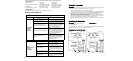
Ajuste del caudal
• Abra completamente las válvulas de cierre de entrada y salida en el calentador, y luego:
• Abra completamente la llave de agua caliente (ej.: bañera) más próxima a la conexión de salida.
• Ajuste la válvula de cierre de salida hasta que el caudal de agua de la llave de agua caliente
coincida con el valor indicado en el Gráfico 1 en la Página 8.
7
¾
Wiring to the unit in Canada
WARNING
The unit must be installed by a qualified electrician, in accordance with the current version of the
Canadian Electrical Code. The unit must be grounded.
IMPORTANT
•
When the PowerStar is not within sight of the electrical circuit breakers, a circuit breaker lockout or
additional local means of disconnection for all non-grounded conductors must be provided that is
within sight of the appliance. (Ref NEC 422.31.)
•
As per the Canadian Electrical Code, C22.1-02 Section 26-744, an auxiliary terminal block must be
fitted to the unit before connecting to the electrical supply. This is available as a kit from BBT, Part
Number "AE Canada Kit". (Contact 866-330-2729).
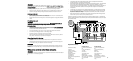
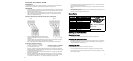
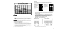
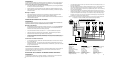
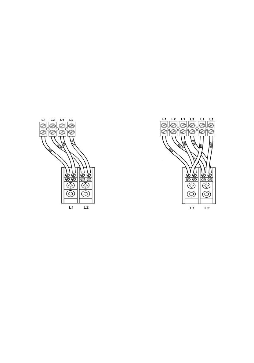
Fitting the auxiliary terminal block (see diagram below).
AE115 AE125
•
Connect the red wires from the left hand terminal of the new block to the L1 terminals in the unit.
(There are two red wires required in the AE115 and three in the AE125).
• Connect the blue wires from the right hand terminal of the new block to the L2 terminals in the unit.
(There are two blue wires required in the AE115 and three in the AE125).
• Push and click the auxiliary terminal block onto the louvered rail in the backplate.
Connecting the supply cable
• The AE115 requires an 80A 240V AC
single phase supply protected by an 80A
double pole circuit breaker.
• The AE125 requires a 120A 240V AC
single phase supply protected by a 120A
double pole circuit breaker.
•
The power cable size and the installation must be in accordance with the Canadian Electrical Code,
C22.1-02.
• The incoming hole diameter on auxiliary terminal block can accept up to 1/0 AWG size cables.
•
The cable entry is via the 1 ¼ inch cable entry hole on the bottom right hand edge of the backplate.
• Strip back the insulation on the power wires about ½ inch. Connect the ungrounded conductors to
the terminals “L1” and “L2” on the auxiliary terminal block.
6