


8
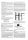
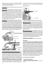
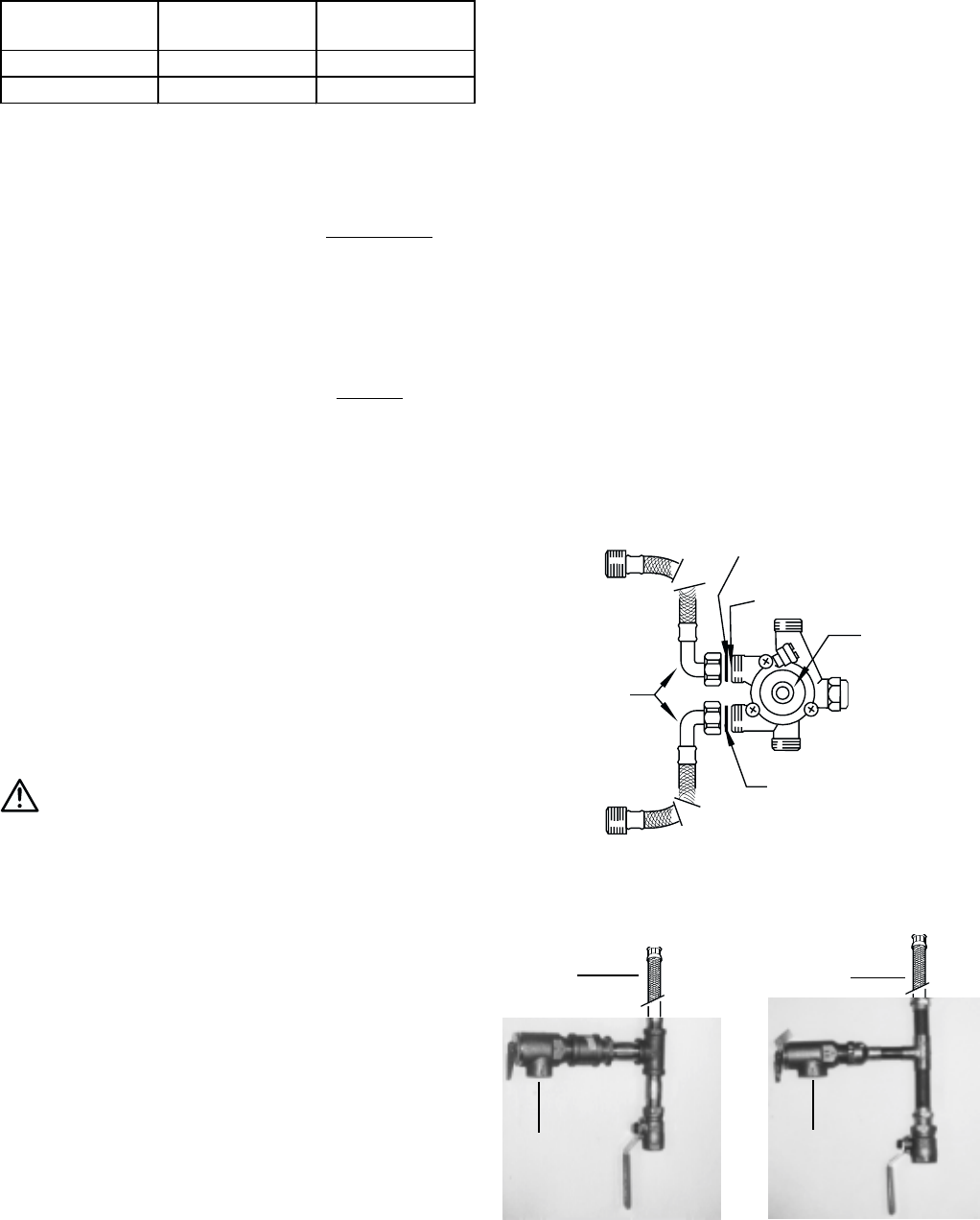
THREADED ASSEMBLY
SWEATED ASSEMBLY
1/2” FLEX
PIPE PRV TO
APPROPRIATE
DISCHARGE
S FITTING
PIPE PRV TO
APPROPRIATE
DISCHARGE
1/2” FLEX
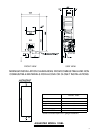
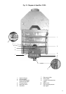
Fig. 6-Plumbing connections for the Aquastar 125BL
NOTE: Do not apply soap solution to pilot filter screen or
pilot orifice area. If you have a leak, shut off the gas. After
verifying that required gaskets are in place, tighten
appropriate fittings to stop leak. Turn the gas on and check
again with a soapy solution. Never test for gas leaks using
a match or flame.
WATER CONNECTIONS
When facing the heater, the cold water inlet is on your right
and the hot water outlet is on your left.
Although water piping throughout your structure may be
other than copper, we recommend that copper piping be
used for at least three feet before and after the heater (follow
local codes if more stringent). Keep water inlet pipe to no
less than 1/2 inch diameter to allow the full flow capacity.
Remember that water pressure must be sufficient to activate
the heater when drawing hot water from the top floor. If the
hot and cold connections to the heater are reversed, the
heater will not function. The AquaStar 125BL is provided
with two flexible type connectors that must be connected
to the inlet and outlet fittings of the water valve as shown in
Figs 5 and 6. ½” Galvanized or brass fittings work best
when connected to the connectors. See Fig 6. These
connectors seal to the water valve by means of a union
connection with a washer type gasket at the joint. No pipe
dope or thread tape is to be used at these joints. Be certain
there are no loose particles or dirt in the piping. Blow out or
flush the lines before connecting to the AquaStar. Full port
valves should be installed on both the cold water feed line
and the hot water outlet line to facilitate servicing the heater.
For installation on a private well system, be sure that the
water pressure is set between 30 and 50 psi.
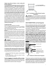
Above 4.500 ft consult your local gas supplier.
Altitude Natural Gas Liquid Propane
inches W.C: inches W.C:
0' - 2.000 ft 5.7" 10.5"
2.000 ft - 4.500 ft 4.6" 8.4"
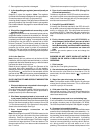
NOTE: The gas pressures specified below refer to
pressures taken at the test pressure nipple on the gas
inlet pipe just above the regulator (See Fig 4). These
readings should be taken while the heater is operating
at full input — i.e. with the gas control positioned all
the way to the right.
MAXIMUM INLET GAS FLOW PRESSURE SETTING
GAS LINE SIZING
-It is strongly recommended that the Natural Gas pipe
be Black Iron pipe the entire distance from the outside
meter to the inlet of the Aquastar regulator. 1/2” Black
Iron pipe up to 10 feet, 3/4” Black Iron pipe up to 40
feet and 1” Black Iron pipe up to 150 feet distances.
Flex line tubing is NOT recommended, but if used
then oversize it.
-It is strongly recommended that the LP Gas pipe be
semi-rigid copper or Black Iron pipe from the outside
regulator to the inlet of the Aquastar regulator. For
semi-rigid copper piping: 5/8” up to 20 feet and 3/4”
up to 60 feet distances. For Black Iron piping: 1/2” up
to 45 feet and 3/4” up to 160 feet distances. Flex line
tubing is NOT recommended, but if used then oversize
it.
THESE FIGURES ARE FOR AQUASTAR SUPPLY ONLY,
ALL OTHER APPLIANCES IN THE BUILDING WILL NEED
TO BE INCLUDED IN THE PIPE SIZING.
National Fuel Gas Code requires that a sediment trap (drip
leg) be installed on gas appliances not so equipped. The
drip leg must be accessible and not subject to freezing
conditions. Install in accordance with the recommendations
of the serving gas supplier.
WARNING: The heater must be disconnected from
the gas supply piping system during any pressure testing
of that system at test pressures in excess of 0.5 psig.
The water heater must be isolated from the gas supply
piping system by closing the manual shutoff valve during
any pressure testing of the gas supply piping system at
test pressures equal to or less than 0.5 psig.
The water heater, including the pressure regulator provided
with it, must not be operated at gas supply pressures in
excess of 0.5 psig. If overpressure has occurred, such as
through improper testing of the gas lines or malfunction of
the supply system, the gas valve and regulator must be
checked for safe operation. Make sure that the regulator
vent is protected against blockage. Vent blockage could
occur during ice storms.
When your connections are made, check for gas leaks at
all joints (not just the ones you made). Apply some soapy
water to all gas fittings and gas valve. Soap bubbles are
a sign of a leak.
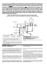
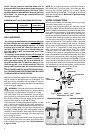
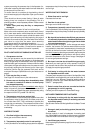
Fig. 5 - Water valve and water
connectors, top view
WASHER
WATER FILTER
WATER VALVE
WASHER
FLEX
CONNECTORS