


7960-233A
Page 1
DESCRIPTION
The CMH-3 is a field installable low pressure control.
The CMH-3 consists of:
1. Installation Instructions 7960-233A
2. Control Assembly 910-1095
3. Low Pressure Control 1804-0107
4. Unit Label 7961-312-0012
For use with all WH182 – WH602 Hi-Boy Wall Mount
Heat Pumps.
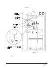
INSTALLATION INSTRUCTIONS
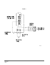
Disconnect all power to unit. Remove control panel
inner and outer covers, and right side condenser inlet
grille. Circled numbers on Figure 2 correspond to
installation instruction steps. Dashed lines indicate that
a wire has been disconnected from this terminal and
reconnected to another terminal.
Use Figure 2 for WH182 to WH361.
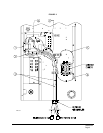
Use Figure 3 for WH421 to WH602.
Step 1. Mount control assembly 910-1095 into control
panel as shown with screws provided. See
Figure 2 or 3, Step 1.
Step 2. Disconnect blue high pressure control wire
from heat pump control terminal LO and
reconnect to terminal #1 of control assembly
910-1095. Route wires through wire holder as
shown in Figure 2 or 3, Step 2.
Step 3. Connect the blue wire from control assembly
910-1095 to LO terminal of the heat pump
control. See Figure 2 or 3, Step 3.
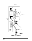
Step 4. Route low pressure control wires up through
the bushing in the bottom of the control panel.
Replace sealing compound after routing wires
through the bushing. Route the wires through
the wire holders in the control panel as shown
in Figure 4. Connect the low pressure control
wires between the terminals #1 and #3 of
control assembly 910-10-9. See Figure 2
or 3, Step 4.
Step 5. Connect the yellow wire from control assembly
910-1095 to Y terminal of the compressor
contactor coil. This is the side of the contactor
coil that the yellow wire is attached to. See
Figure 2 or 3, Step 5.
Step 6. Connect the black wire from control assembly
910-1095 to C terminal of the compressor
contactor coil. This is the side of the contactor
coil that the black wire is attached to. See
Figure 2 or 3, Step 6.
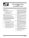
Step 7. Remove service port cap on the suction line.
Install the low pressure switch on the suction
line. Check for pressure at the flare tee dill
valves after installation to insure that the dill
valve in the unit service port was depressed by
the flare tee connector. Check for leaks at the
flare tee connectors. Replace service port
cap on the flare tee service port and tighten.
See Figure 4.
Step 8. Recheck all wiring. See Figure 1. Check for
proper operation of the unit by energizing in
cooling mode. Run for five minutes. Unit
should not go into lockout.
Step 9. Apply “This unit equipped with CMH-3 control
module” label to the inside of the inner control
panel cover above the wiring diagram.
Step 10. Replace all panels and covers. This
completes installation.
INSTALLATION INSTRUCTIONS
CMH-3
LOW PRESSURE CONTROL
Bard Manufacturing Company
Bryan, Ohio 43506