PRO-PDLVS
VAN SLIDING DOOR
POWER LOCK SWITCH
PRE-INSTALLATION:
1. Check and be certain that when the sliding door is fully closed the distance between the door and the jam is no greater
then 1/2". This will insure proper contact when the switch is installed.
NEW: Included with this kit are two 10º angled plates. These are intended for use in vans where the door meets the post
at an angle, ( Some Chrysler, Ford, and Chevrolet Mini Vans). The plate(s) are to be installed on the spring contact side
between the gasket and spring contact, in addition, any combination may be used. For example, 1 plate will accommodate
a 10º angle, 2 plates will accommodate a 20º angle and the two plates placed opposing each other will allow you to
accommodate a closed door gap wider than 1/2".
2. Check behind your intended mounting location to insure adequate clearance. Consideration must be made for both the
spring loaded contacts which will be mounted in the Van's sliding door, and the striker plate which will be mounted in
mating door jam. For reference, a minimum inside clearance of 2 1/2" is required for the spring contacts, and a minimum
inside clearance of 1" is required for the striker plate. This allowance will facilitate wiring the switch and prevent shorts.
INSTALLATION:
Mount the door spring contact side first:
1. Using the gasket provided as a template, draw the center oval on the sliding door where you intend to mount the switch.
Place the template provided over the marked location and center punch the two holes and two mounting screw holes.
2. Drill two 7/16" holes in the pre-marked oval area where the switch will pass through.
3. Drill two 1/8" inch holes in the pre-marked screw mount locations.
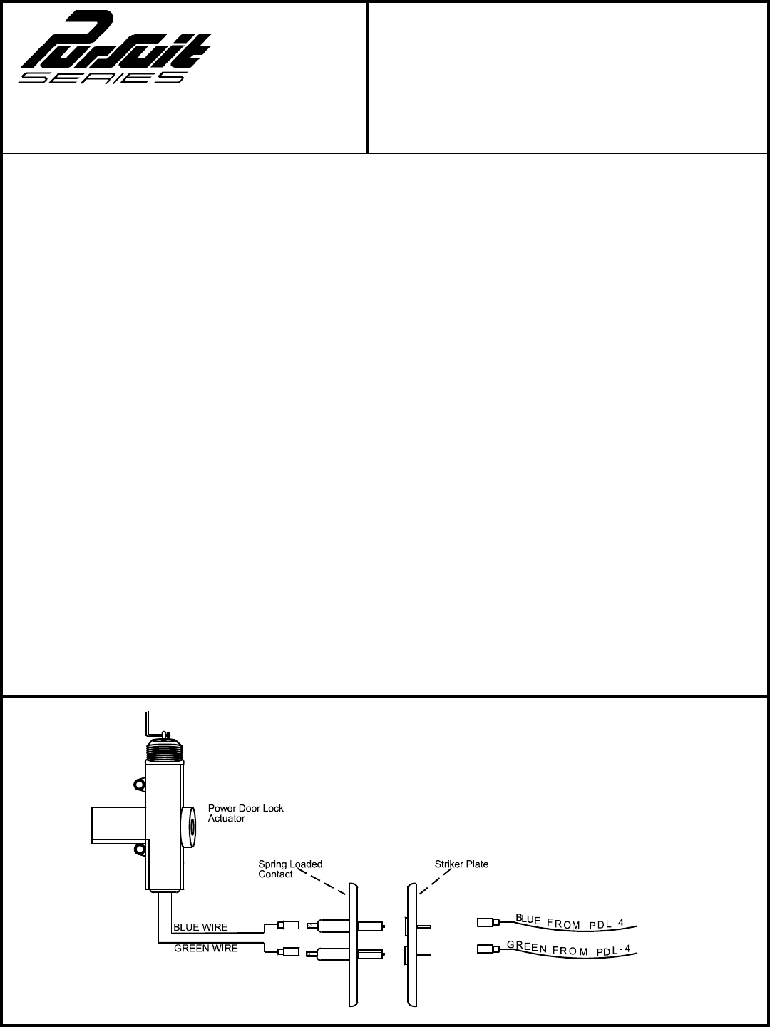
4. Pass the two wires through cup shaped gasket and connect the two actuator wires to the switch using the female spade
terminals and rubber boots provided.
5. Mount the spring contact in the door and secure it with the two screws provided.
Mounting the Door jam striker plate:
1. Coat the contact of the spring switch with lithium (white) lube and close the sliding door. When you open the door again,
you will find two marks on the jam side where the contacts met it.
2. Using these marks as a guide, center the striker plate template between the two marks and center punch a mark where
the two male terminals will pass through, also center punch the two mounting holes.
NOTE: Minimum 1/2" hole must be drilled for the terminals to pass through to insure clearance for the terminals and to
prevent shorts.
3. Drill the 1/2" hole for the terminal pass through, also drill the two 1/8" mounting screw holes.
4. Pass the two ( Blue and Green) wires from the PDL-4 control module through the striker gasket and attach them to the
terminals of the striker plate.
5. Mount the striker plate and gasket to the door jam using the two screws provided.
Again lubricate the switch contacts, close the door, and confirm that the contacts meet the striker plate.
Check for proper operation of the actuator by operating the door locks from either door lock switch.
INST ALLATION GUIDEFOR:
Form No. 128-5044


