REMOTE
POWER DOOR LOCK
INTERFACE
PRE-INSTALLATION CHECKS:
1. This module is designed to interface with any Remote Security System with Ground Pulsed door lock outputs. When interfacing to AUDIOVOX
SECURITY Products, verify that the 2-wire door lock output connector from the alarm module is loaded with a Red and a Green wire.
NOTE: If the 2-pin door lock output connector from the Alarm Module is loaded with a Red and Black wire, you must use the model AA-9158
Door Lock Interface.
2. This module will require the addition of the optional "PDA-1" Kit in these types of Power Door Locking Systems.
a. Vacuum operated power door locks.
b. Door locking systems requiring key locking of drivers door in order to automatically lock all other doors.
INSTRUCTIONS:
1. Remove the driver's door panel for access to existing power door lock switch wiring.
2. Mount the module in the kick panel area of the driver's side of the vehicle.
3. In most vehicles, the door lock wires can be found in the driver's kick panel after examining the switch. If not, route the wires into the driver's
door using the existing wiring tube as access.
4. Examine the existing power door lock switch in the driver's door to determine which wiring method must be used. The door switch will be
one of the following:
a. 3-Wire positive switched lock (Most GM vehicles).
b. 3- Wire negative switched lock (Some Ford and Foreign vehicles).
c. 4 or 5 Wire polarity reversal lock (Most Fords and Chryslers and some GM).
5. The use of a voltage test meter will be required to determine which of the three types of switches is in your vehicle.
a. 3-Wire positive switched locks: One wire will be 12 volt positive at all times, one will be 12 volt positive when the switch is in the "lock" mode,
and the last will be 12 volt positive when the switch is in the "unlock" mode. (The AS-9159 Door Lock Interface is NOT required for this
application if using the APS 100, APS 200, APS 300, PRO 9244, or PRO 9249 Security Systems).
b. 3-Wire negative switched locks: One wire will be Grounded at all times, one wire will be Grounded when the switch is in the "lock" mode,
and the last will be Grounded only when switch is in the "unlock" mode. (AS-9159) Door Lock Interface is not required).
c. 4 or 5 Wire polarity reversal locks: One wire will be 12 volt positive at all times, one or two wires will be Grounded at all times. All the remaining
wires will be positive 12 volt when the switch is in one of two positions (lock or unlock) and will reverse to Ground when the switch is moved
to the other position, (in some cars, they will be 12 volt positive in the "lock" position and Ground in the "unlock" position or just the opposite
in other cars).
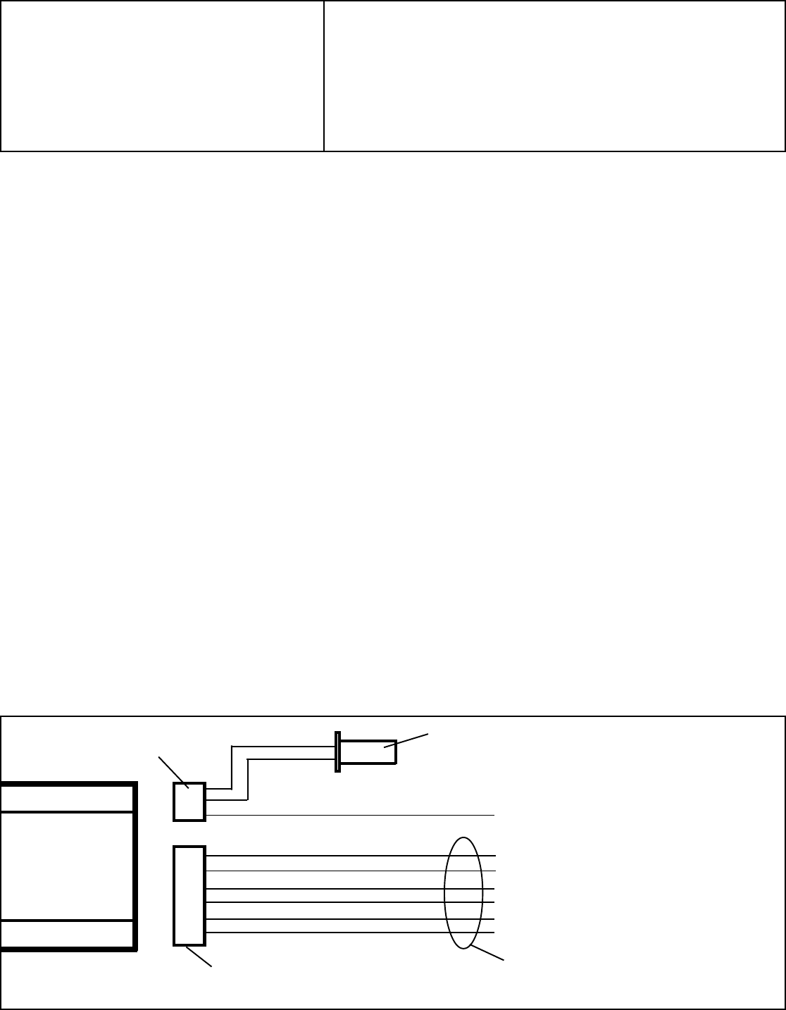
6. Connect the Red w/White wire from the AS 9159 Door Lock Interface to a +12 VDC battery source at the fuse box.
7. Plug the 2-pin Red and Green wire connector into the mating connector from the alarm module.
NOTE: When using with PRO 9244, PRO 9249, APS 100, APS 200, or APS 300, it will be necessary to splice directly to the Door Lock Outputs.
8. Plug both the 4 pin and the 6 pin connectors into the AS-9159 module.
9. Refer to the applicable wiring schematic in the remote power door lock wiring supplement for connection of Green, Blue, White, Yellow, Orange
and Blue w/White stripe wires.
ORANGE
BLUE
BLUE w/WHITE
GREEN
YELLOW
WHITE
REFER TO THE REMOTE POWER DOOR
LOCK WIRING SUPPLEMENT FOR
CONNECTION OF THESE WIRES.
AS-9159
MODULE
6-WIRE HARNESS
2-PIN CONNECTOR- PLUG ONTO MATING 2-PIN CONNECTOR
FROM ALARM MODULE
* NOTE: IF THE WIRE COLORS FROM THE ALARM MODULE
ARE RED AND BLACK, YOU MUST USE AA-9158
DOOR LOCK INTERFACE
RED
TO 12 VDC CONSTANT SOURCE
3-WIRE HARNESS
Model: AS-9159
AUDIOVOX SECURITY
GREEN
Audiovox Corp., 150 Marcus Blvd. Hauppauge, N.Y. 11788
INSTALLATION GUIDE FOR:
Printed in Taiwan
Form No. 128-4155B
RED w/ WHITE
Rev. B - Added "Red w/White " wire to #6 and Diagram. 3-23-95.


