


TH150 400-150-000-C 5/9/06 1/6
1. Introduction
The TH150 Series electronic thermostat is designed for low-voltage
pressure-dependent variable air volume (VAV) applications. It
comes in four different models:
Depending on the model, the TH150 thermostat can have up to
three outputs connected to the following control devices:
actuators
thermal valves (N.O. and N.C.)
solenoid valves
solid-state relays (SSRs)
silicon-controlled rectifiers (SCRs)
mechanical relays
contactors
Accessories
RC840 or RC840T electromechanical relay
RT850 or RT850T solid-state relay
AC146-410 temperature sensor
AC144-03 temperature sensor
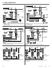
2. Installation
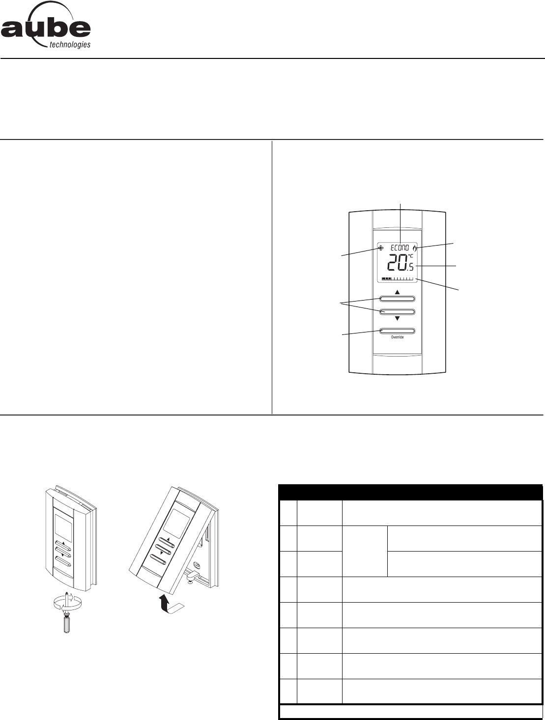
2.1 Mounting Instructions
n Remove the thermostat from its base by unscrewing the cap-
tive screw and tilting the bottom of the thermostat up. The
screw cannot be completely removed.
o Pass the wires through the center hole of the base and secure
the base to the wall or onto an electrical box.
p Wire the thermostat. See section 2.2 for terminal designations
and section 3 for typical wiring diagrams.
q Reinstall the thermostat onto its base and secure with the cap-
tive screw.
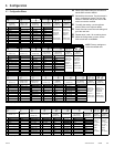
2.2 Terminal Designations
The designations of the terminals vary according to the particular
model of thermostat. Refer to the following table for the description
of each terminal.
• TH150-1A • TH150-1F
• TH150-1A2T • TH150-1F2T
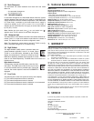
Configuration and status display
Heating mode
Temperature display
Output power display
Temperature
adjustment
button
Cooling mode
Override button
TERMINAL DESCRIPTION
1
2
24 VAC
COM
Power supply
3
4
AN1
COM
Output 1
Models TH150-1A and TH150-1A2T
3
4
OPEN
CLOSED
Models TH150-1F and TH150-1F2T
5
6
T2/AN2
T2/COM
Output 2 (models TH150-1A2T and TH150-1F2T)
7
8
T3
T3
Output 3 (models TH150-1A2T and TH150-1F2T)
9
10
COM
SENSOR
External sensor input. (For applications requiring
an external sensor, see section 4.2.)
9
11
COM
C-Over
Mode Changeover input (N.O. contact). See sec-
tion 5.5.2.
9
12
COM
NSB
Night Setback activation input (N.O. contact).
See section 5.6.
Note: To configure the terminals, see section 4.
TH150 Series
Installation and User Guide
VAV Thermostat