TH144 400-144-003-C 2008-02-08 1/6
TURN OFF POWER TO THE SYSTEM AT THE MAIN POWER
PANEL TO AVOID ELECTRICAL SHOCK
.
Installation should be carried out by an electrician or a qualified
technician.
1.1 Find a Location for the Thermostat
• For a new installation, choose a location about 5 ft. (1.5 m) above
the floor and on an inside wall.
• Avoid locations where there are air drafts (top of staircase, air out-
let), dead air spots (behind a door), direct sunlight, concealed
chimneys or pipes, or air diffusers.
1.2 Prepare and Connect the Thermostat
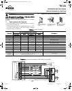
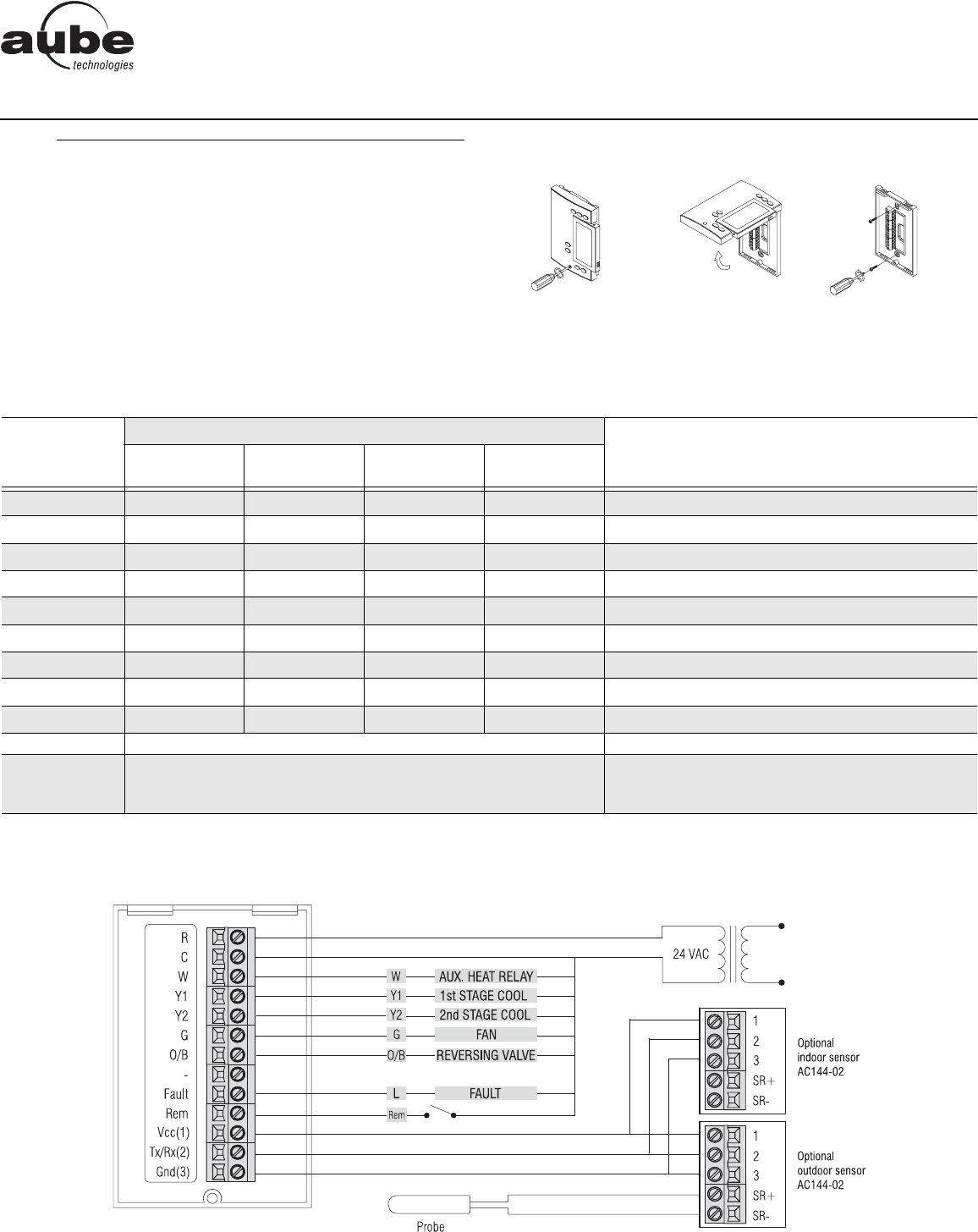
TABLE 1: Wiring Terminals
FIGURE 1: Typical Wiring Diagram (model shown TH144-3H2C)
n
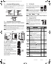
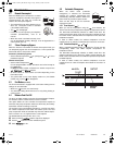
Installation
1.
Loosen the captive screw
holding the base to the
module.
Gently lift the lower part of
the module to remove it
from the base.
Secure the base using the
wall anchors & screws.
Wire the thermostat.
Terminals
OUTPUT CONFIGURATION (MODEL)
Connect to...
1H1C
Geothermal
2H1C
2H2C
Geothermal
3H2C
R
D D D D
Supply 24 VAC
C
DDDD
Common
W
D D
Auxiliary heat relay
Y
DD
Compressor relay
Y1
D D
First compressor relay
Y2
DD
Second compressor relay
G
D D D D
Fan relay
O/B
DDDD
Reversing valve
Fault
D D D D
Heat pump fault output
REM Unoccupied input (optional) - see 1.3 CT240/CT241/timer
Vcc (1)
Tx/Rx (2)
Gnd (3)
AC144-02 Remote Indoor and Outdoor
Temperature Interface - see 1.4
AC144-02
a
a. For 2H1C & 3H2C models, the AC144-02 is required to use the balance point option (compressor cut-off).
TH144
Installation and User Guide
Electronic Thermostat for a Heat Pump
400-144-003-C (TH144_HP) ENG.fm Page 1 Friday, February 8, 2008 10:29 AM