


400-230-000-D 2/7/07 1/2
1. Introduction
This master and slave unit system is specially
designed for large floor heating applications
exceeding 15 A.
The master thermostat controls a single or
multiple floor heating zones driven by slave units.
The master thermostat can control up to 10 slave
units.
Each slave unit drives its own zone and is
equipped with a GFCI test button and warning
light as well as an On/Standby switch to facilitate
maintenance on specific zones of the floor
installation.
2. Operation
Master Thermostat
The master unit controls the temperature and
sends a signal to slave units when heating is
required. The floor sensor is connected to the
master unit. The master unit is powered by the
slave units.
Slave Unit
The slave unit receives the signal sent by the
master unit and activates its load.
NOTE: There must be a minimum of one slave
unit ON to power the master unit.
3. Installation
Turn off power to the heating system at the
main power panel to avoid electrical shock.
Installation should be carried out by an
electrician.
3.1 Wiring Guidelines
• The wire distance between the master thermo-
stat and slave unit should not exceed 500 ft.
(150 m).
• The floor sensor cable should not exceed
200 ft. (60 m).
• A 3-wire 20 AWG cable is recommended.
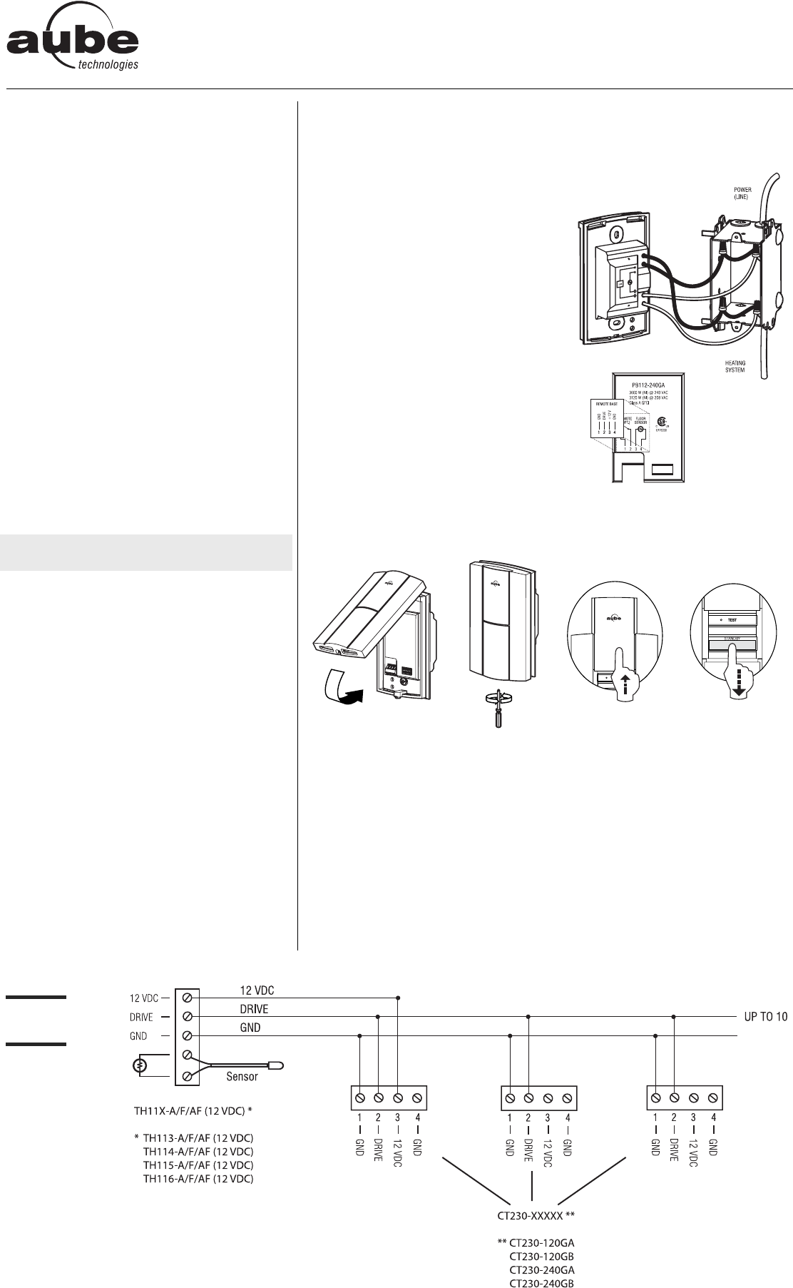
3.2 Slave Units - Installation and Wiring
The slave units can operate on different voltages (e.g. 5 units @ 120 V and 5 @ 240 V).
• Required parts: CT230-120GA, -120GB, -240GA or -240GB
• Installation: On an electrical box
• Location: Installation near the master
thermostat is not required (i.e. can be
installed in a utility room).
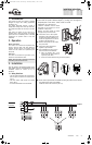
• Wiring: The power bases are joined
through a daisy chain connection.
n Connect the 120 V or 240 V power
base wires to the power (line) and to
the load (floor) using solderless con-
nectors for copper wires, and secure
the base to the electrical box.
o Affix the wiring sticker (in the CT230
box) to the base.
p Connect the slave power bases
together as per FIGURE 1.
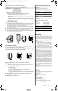
q Once installation and wiring is com-
plete, mount the CT230 interface:
a) Align the bracket tabs of the
CT230 with the holes located on
top of the power base.
b) Secure the CT230 interface using the screw (captive).
r Switch all slave power bases to STANDBY by sliding the protective door upwards
and positioning the switch to STANDBY.
Install and connect the master unit (see 3.3).
MASTER THERMOSTATS
TH113-A/F/AF (12VDC)
TH114-A/F/AF (12VDC)
TH115-A/F/AF (12VDC)
TH116-A/F/AF (12VDC)
FIGURE 1
Connections
Installation Instructions
SLAVE UNITS
CT230-120GA
CT230-120GB
CT230-240GA
CT230-240GB
400-230-000-D (PB112-12VDC) ENG.fm Page 1 Wednesday, February 7, 2007 9:11 AM