


4
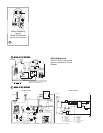
1. Route wiring to left side of furnace.
2. Remove junction box cover.
3. Connect 120 white wire to furnace 120 white wire.
4. Connect 120 black wire to furnace 120 black wire.
5. Connect ground wire to furnace green ground wire.
After field hookups have been made, put wire connections into
furnace junction box and replace cover.
6. Connect thermostat leads to the two blue furnace thermostat leads.
NOTE: Furnace is equipped with a 120 volt AC motor. All other
electrical component parts are supplied with power from a trans-
former inside the furnace at 24 volts AC.
NOTE: A 120 volt model can also be supplied with a 30 inch
power cord attached from the factory supplied with a molded plug
with ground pin.
NOTE: DC units are supplied with a power switch
which when turned OFF for servicing will remove power through the
furnace wiring. Switch must be in ON position for furnace to operate.
See
FIG 3-G. AC units switch is in valve circuit only.
POWER SUPPLY
Atwood Mobile Products highly recommends the use of an electronic
(solid state) converter with clean, clear power output. This will assure
the life of the electronic controls and motor life could be extended as
much as 500% beyond typical linear converter applications.
THERMOSTAT INSTALLATION
The thermostat is very sensitive. HANDLE WITH CARE AT ALL TIMES.
Locate thermostat 48˝ to 54˝ above floor on an INTERIOR wall away from
areas of abnormal heat or cold. EXTERIOR wall location must have a 3/4˝
spacer between thermostat and exterior wall.
Follow manufacturer’s installation instructions provided with thermo-
stat. When a thermostat is not supplied use a thermostat rated for 12
VDC or 24 VAC minimum lamp.
CONVERTIBLE GAS CONTROL FIG 6
LC MODEL UNITS come equipped with a convertible gas control. Each
unit is supplied with two main burner orifices. One will be in place, the
other will be attached to blower housing cover. Each orifice will be
clearly marked with a drill size as shown below.
GAS TYPE BTU/HR LINE PRESSURE VALVE REGULATOR DRILL SIZE
PROPANE (LP) 40,000 11˝ W.C. 10.5˝ W.C. 49P
NATURAL (NAT) 40,000 7˝ W.C. 3.5˝ W.C. 30N
PROPANE (LP) 35,000 11˝ W.C. 10.5˝ W.C. 51P
NATURAL (NAT) 35,000 7˝ W.C. 3.5˝ W.C. 32N
The pressure settings of the convertible valve are set for natural gas
NAT 3.5˝ W.C. or LP 10.5˝ W.C. and are not adjustable. Use Loctite
#RC609 on orifice threads when installing a new orifice. 1/8˝ NPT plug
is provided upstream of gas connections for checking gas pressure.
VALVE CONVERSION (FIG. 6)
1. Check exposed section on side of adjustment plug to determine
whether it is set for natural or propane. NAT is stamped on one end
and LP is stamped on the other end of plug. The types of gas in use
will be showing right side up.
2. Unscrew plug and remove from valve tower.
DO NOT remove rod from
tower or make any adjustments.
3. A. When set for LP and NAT is required:
Rotate plug and replace into valve tower.
NAT
SHOULD NOW BE VISABLE FIG
6
B. When set for NAT and LP is required:
Rotate plug and replace into valve tower.
LP
SHOULD NOW BE VISABLE FIG 6
4. Check rod for proper positioning while tightening plug into tower.
The plug, which has been factory calibrated for this valve only,
should be reinstalled finger tight.
DO NOT USE PLUG ON ANY OTHER VALVE.
INSTALL ONLY THE CORRECT MAIN BURNER ORIFICE FOR TYPE OF GAS BEING USED.
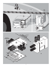
ORIFICE REPLACEMENT
1. Unit will need to be removed if installed, if not start with step #2.
2. Remove burner cover and extended manifold.
3. Remove burner assembly from control box.
4. Remove two screws holding burner head in place.
5. Use a 7/16˝ socket to remove orifice and replace correct orifice cor-
responding to type of gas required, which corresponds to regulator
plug setting
FIG 6.
6. Replace burner head with two screws.
7. Reinstall burner assembly. Burner assembly must seal tight against
control box.
8. Install extended manifold and apply thread sealant to threads going
into gas valve.
9. After converting furnace,
IN PLAIN SIGHT, put “CONVERTED” sticker (pro-
vided in your conversion packet) on rating label.
SYSTEM CHECKS
ƽ WARNING
FIRE OR EXPLOSION
• Never check for leaks with an open flame.
DIAGNOSTIC CHART
FAULT LED INDICATION
Internal Circuit Board Failure Steady on, no flashing
Limit switch/Airflow problems 1 flash with 3-second pause
Flame Sense Fault 2 flashes with 3-second pause
Ignition Lockout Fault 3 flashes with 3-second pause
PROPANE GAS PRESSURE TEST
The furnace and any individual shut-off valve must be disconnected
from gas supply piping system during any pressure testing of system
at test pressures of more than 1/2 PSI.
Before furnace is connected, piping systems must be tested to be leak
free. The test must maintain air pressure of at least 6˝ of mercury or 3
PSI for at least 10 minutes.
The entire piping system must be maintained within a range of 10-14˝
W.C. when all appliances are in operation. Test the gas connections for
leakage with a leak test solution.
STATIC PRESSURE TEST
CASING STATIC PRESSURE TABLE
If duct static pressure cannot be set, casing static pressure should not exceed
the values listed below when taken cold.
DUCTING SYSTEM OPERATING VOLTS FLEXIBLE HARD
DC MODELS 12 0.25˝ W.C. 0.35˝ W.C.
AC MODELS 120 0.25˝ W.C. 0.35˝ W.C.
NOTE: For maximum performance and reliability refer to Installation Addendum
for manufacturer’s recommendations and specifications.
Voltage greater than indicated will cause higher static readings.
Reducing the number of duct turns and stretching ducts will increase
air flow and reduce static pressure. Adding ducts or increasing dis-
charge system (hard ducting) will also reduce static pressure.
NOTE: Special tool required to take casing static pressure. Location for
Static Pressure Tap for casing is located on back of casing (top left
corner)
FIG 3.