


3
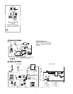
4. Insert furnace from backside of wall. Line up hole in wall and furnace.
5. Apply sealant to back of vent ring and vent cap base.
6. Install vent assembly with HOT at top for horizontal and on right
side for vertical installation (
FIG 1-1A). Slip vent into combustion air
intake tube. Secure to wall with four (4) screws.
7. Vent must have a minimum 1-1/4” over lap on exhaust tube and a
minimum 1/2˝ overlap on combustion airtube.
8. Horizontal units - secure to floor with two (2) screws through legs
on back of casing. Vertical units use vertical mounting brackets and
self-tapping screws to hold furnace to floor (tabs on control box can
be used also to secure furnace).
DUCTING - HORIZONTAL & VERTICAL (FIG 3-4A)
HORIZONTAL
PROPER DUCT INSTALLATION IS CRITICAL TO THE OPERATION OF THIS FURNACE
CONTINUOUS USE MATERIALS RATING
DUCTS 9˝ IN LENGTH OR MORE 200˚F.
4˝ DUCTS LESS THAN 9˝ IN LENGTH 250˚F.
METAL BOOTS LESS THAN 9˝ IN LENGTH 250˚F.
Ducting systems can include any combination of discharge openings, as
long as static pressure and minimum discharge area requirements are met.
ALL MODELS - (also see STATIC PRESSURE TEST)
REQUIRED MINIMUM DISCHARGE 48 IN
2
REQUIRED MINIMUM RETURN AIR 80 IN
2
• See MINIMUM CLEARANCE TO FLOORBOARDS, WALLS & SIMILAR COMBUSTIBLE
BUILDING MATERIALS.
• Each 4-inch duct opening provides 12 in
2
of discharge area. Provide
an extra 12 in
2
of non closeable duct discharge area for each
closeable register used.
• Use of 2˝ ducts does not count toward achieving min. discharge req.
Ducting in dead air space with no return air, such as holding tank
areas, does not count toward achieving min. discharge requirements.
• Adjust ducting installation to obtain air rise of 100˚F - 130˚F.
Flexible Ducting System
When designing Flexible Duct Systems:
• avoid sharp bends or crushed ducts
• stretch all ducts and run them directly to outlets, keeping quanti-
ty and angles of bends to a minimum
1. Remove knockout plates from desired outlets.
2. Attach duct adapter to each opening, by inserting flange over casing,
locking tab into casing slot and turning adapter 90˚.
3. Attach and secure
FOUR-INCH flexible ducts to adapters.
4. Run ducts to desired location within RV, secure to registers.
5. Additional ducting may be needed to maintain static pressure.
Hard Ducting Floor System
When designing Hard Duct Systems:
• undersize ducting will cause high temperature limiting
• oversize ducting will cause inadequate air flow from registers
• when hard ducting is 1-1/2˝ in depth, an additional flex duct may
be needed to maintain installation static requirements
•
DO NOT install floor registers within 2 feet of return air openings.
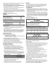
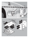
OPTIONAL INSTALLATION - BOTTOM DISCHARGE (FIG 4-4)
1. Remove bottom discharge cover plate. This ducting option must
be connected to a ducting system. FIG 3 (parts breakdown) #40 -
GASKET AND PLENUM PLATE KIT is available when attaching furnace.
2. If cutout is required:
FLOOR CUTOUT
BOTTOM DISCHARGE ABCD
HORIZONTAL-WITHOUT DOOR (FIG 4) 18-20 1/2˝ 5-1/2˝ 10-1/2˝ 3/4˝
3. Fasten plenum plate (4-E) over floor cutout. If a gasket and
plenum plate are not used, seal furnace to hard duct system mak-
ing sure seal is air-tight, continue with STEP 5.
4. Position gasket (4-F) on plenum plate.
5. Set furnace on gasket, gasket must remains in position.
Use additional ducting to maintain correct static pressure.
VERTICAL
The only ducting option, when using vertical installation, are the top
two ducts and tw ducts off the back of the casing. This is the only
configuration allowed with vertical installation (
FIG 3A).
GAS CONNECTION
1. Connect gas line to fitting on top rear of furnace. Be sure all male
pipe threads, other than flare fittings, are treated with a sealing com-
pound resistant to the action of propane (LP) gas.
DO NOT put sealing
compound on flare fittings.
2. A 3/8˝ flared fitting connection is provided for supply connection to
furnace. The gas supply line of the furnace must be of adequate size
to provide 11˝ W.C. gas pressure. This pressure must be maintained
under maximum flow conditions with all gas appliances in operation.
3. Use two wrenches to hold fitting and flare nut when tightening gas
line to fitting. (
FIG. 2
)
ELECTRICAL CONNECTION (FIG 5)
ƽ WARNING
INJURY OR PROPERTY DAMAGE
• Label all wires before disconnecting for service. Wiring errors can
cause improper and dangerous operation.
Verify proper operation after servicing.
• Disconnect electrical power before servicing.
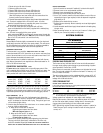
Conductor Sizing Table - MAX. 10% VOLTAGE DROP - (12 VDC)
CURRENT DRAW (AMPS)
8 9 10 15 20
GAGE MAX. LENGTH OF SAE CONDUCTOR (IN FEET) FROM SOURCE TO DEVICE
18 21 19 17 11 9
16 33 29 26 17 13
14 52 46 41 28 21
ƽ CAUTION
PROPERTY DAMAGE
• This connection is for low-voltage battery or direct current only. Do
not connect to 120- or 240- volts AC.
This unit is designed for negative ground 12 volt DC ONLY. Polarity
must be observed so furnace motor will run in proper rotation. DO NOT
attempt to alter to a positive ground system.
12 VOLT DC MODELS
Route 12 volt DC and thermostat leads to left side of control box. Use
a minimum of 18 GA wire to minimize voltage drop. The furnace must
be installed so electrical components are protected from water. To
make electrical connections: see
WIRING DIAGRAM FIG 5
1. Route wiring to left side of furnace.
2. Connect red wire to positive side of power supply.
3. Connect yellow wire to grounded side of power supply.
4. Connect blue wire marked positive thermostat to + side wire of
thermostat using 22-18 GA stranded wire.
5. Connect the other blue wire to the other thermostat lead using
minimum 22-18 GA stranded wire.
See instruction with thermostat for complete wiring directions.
For best furnace performance when power supply is from a converter
equipped with a charging port, wire the converter to furnace parallel
with battery. This provides consistent voltage to furnace, increasing
component life, filtering power surges and AC spikes
120
VOLT AC MODELS
Route 120 volt AC and thermostat leads to wires located on the left
side of control box using a minimum of 18 GA wire. The furnace must
be installed so electrical components are protected from water. To
make electrical connections see WIRING DIAGRAM FIG 5.