


3
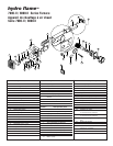
be in front of door to furnace. Provide an access opening for service
and/or removal of furnace. The furnace must be side ducted (NO front
discharge). Secure furnace to floor with one screw
FIG 4-J.
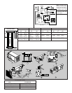
5. Remove cover plate from furnace FIG 4-D. To install duct adapters for
side discharge models, insert back flange over casing and insert tab
into square notch, then twist adapter 180˚ FIG 4-E.
6. Insert furnace into cabinet opening and secure with two screws
through holes in control box flanges
FIG 5-A.
7. For side duct applications, slide 4˝ flexible ducting material over
duct adapters and secure FIG 3.
VENTING
1. To install extension box FIG 4-C, apply mastic or sealant to back of
flanges on box. Slide through outside wall cut out and into furnace
air channel.
DO NOT FORCE OR BEND PARTS
.
2. Apply mastic or sealant to the top and sides of outer edge of vent
cap.
DO NOT PLUG HOLES. Slide assembly over furnace exhaust tube FIG
4-B, push into wall and secure with two screws. Note that bottom
flange is not sealed to allow water drainage.
3. The extension box has no minimum clearance requirement FIG 4-C.
4. The vent outlet shall be installed as to be in the same atmospheric
pressure zone as the combustion air intake. No modification of vent
system is allowed.
ƽ WARNING
CARBON MONOXIDE POISONING
• Properly seal vent system preventing carbon monoxide from entering
coach.
5. Install return-air system to ensure negative pressure, created by the
circulating blower, does not effect another appliance’s combustion
air supply or act to mix products of combustion with circulating air.
All appliances in the furnace cabinet must be directly vented outside.
DIRECTIONAL AIRBOX INSERT (FIG. 7)
1. Remove front door of furnace.
2. Follow shutdown procedure instructions affixed to furnace.
3. Remove sheet metal screw holding circuit board plate to air box.
Retain to fasten Air Box Insert to bottom of air box
FIG 7-A.
4. Install Air Box Insert into air box (pay attention to the direction you
would like warm air diverted). Make sure two holes in Air Box Insert
line up with existing holes in air box
FIG 7-B.
5. Fasten Air Box Insert to top of air box using a 1/4˝ long #6 sheet
metal screw. Fasten bottom of Air Box Insert and circuit board plate
to bottom of air box using the screw removed.
6. Follow lighting instructions to place furnace in operation.
7. Replace front door on furnace.
PROPANE GAS CONNECTION (FIG. 5)
Connect gas line to brass fitting on left side of furnace. Be sure all
male pipe threads, other than flare fittings, are treated with a sealing
compound resistant to the action of propane (LP) gas.
DO NOT put seal-
ing compound on flare fittings.
1. Insert gas line through hole on left side.
2. Connect gas line to brass fitting inside furnace casing immediately
ahead of gas control valve
FIG 5-B.
3. A 3/8˝ flared fitting connection is provided at gas control valve inlet for gas
supply connection to furnace. The gas supply line of furnace must be of ade-
quate size to provide 11˝ W.C. gas pressure. This pressure must be main-
tained under maximum flow conditions with all gas appliances operating.
4. A 1/8˝ N.P.T. plug is accessible for test gauge connection on gas
valve assembly
FIG 5-H.
5. Use two wrenches to hold brass fitting and flare nut when tightening
gas line to brass fitting. DO NOT twist valve assembly FIG 6.
ELECTRICAL CONNECTION
ƽ WARNING
INJURY OR PROPERTY DAMAGE
• Label all wires before disconnecting for service. Wiring errors can cause improper,
dangerous operation. Verify proper operation after servicing.
• Disconnect electrical power before servicing.
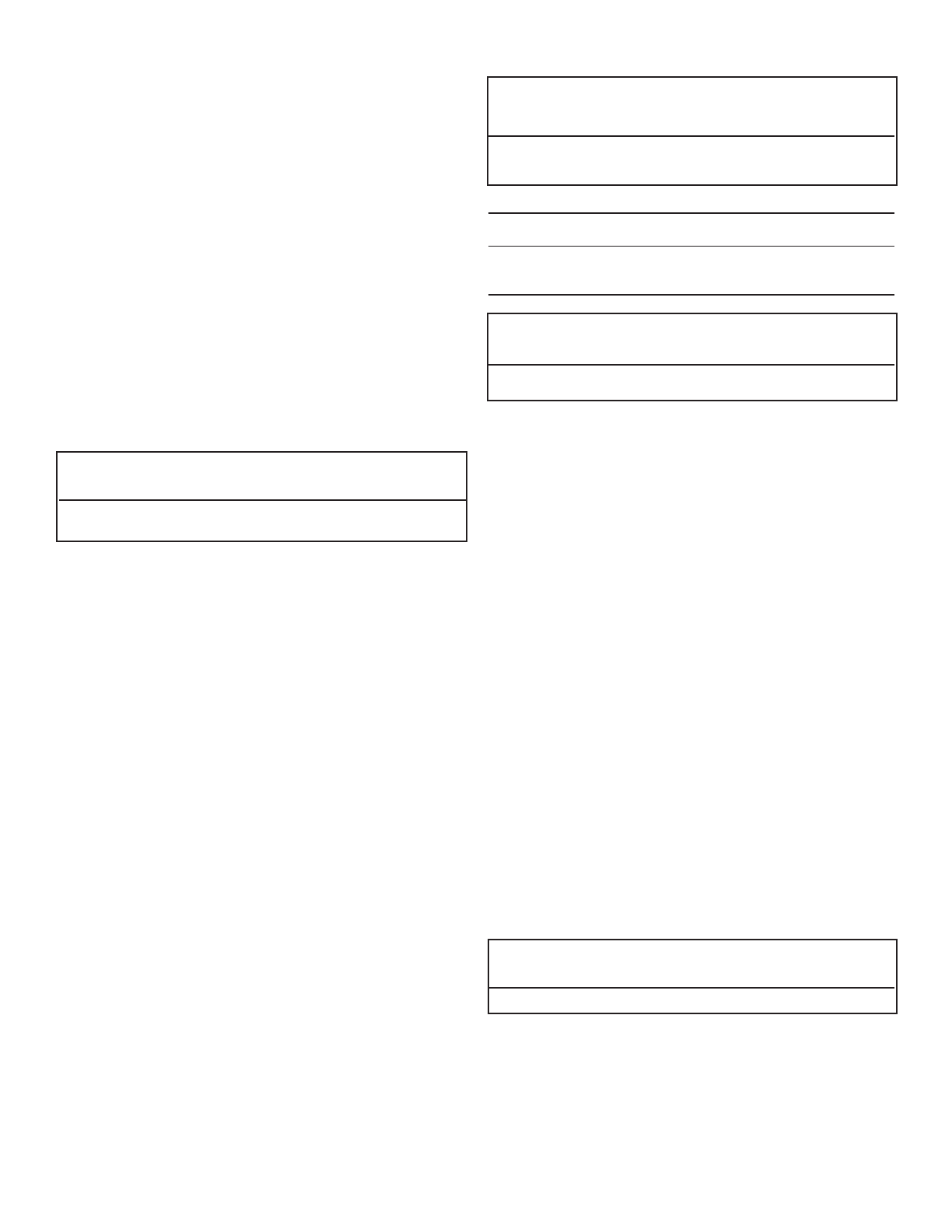
Conductor Sizing Table - MAX. 10% VOLTAGE DROP - (12 VDC)
CURRENT DRAW (AMPS)
34567891015
GAGE MAX. LENGTH OF SAE CONDUCTOR (IN FEET) FROM SOURCE TO DEVICE
18 61 45 36 30 26 23 20 18 12
16 96 72 58 48 41 36 32 29 19
ƽ CAUTION
PROPERTY DAMAGE
• This connection is for low-voltage battery or direct current only. Do not
connect to 120- or 240- volts AC.
This furnace is designed for negative ground 12 volts DC only. DO NOT attempt to
alter furnace for a positive ground system or connect furnace directly to 120
volts AC. Damage to furnace components will occur and warranty will be voided.
Use a minimum of 22-18 GA wire to minimize voltage drop. The furnace must
be installed so electrical components are protected from water. To make electri-
cal connections:
SEE WIRING DIAGRAM FIG 8
1. Remove screw from junction box on right side of furnace FIG 5-B.
2. Route wiring to right side of furnace.
3. Connect red wire FIG 5-C to positive side of power supply.
4. Connect black wire
FIG 5-D to grounded side of power supply.
5. Connect white wire from furnace to thermostat
FIG 5-E.
6. Connect thermostat wire from thermostat to +12VDC of power supply
FIG 5-F.
7. Reinstall junction box cover FIG 4-F.
For best performance of furnace when power supply is from a converter equipped
with a charging port, wire the converter to furnace parallel with battery. This pro-
vides consistent voltage to furnace, increasing component life, filtering power
surges and AC spikes
FIG 4-G & H.
NOTE: All units are supplied with a power switch which when turned off for
servicing will remove power through the furnace wiring. Switch must be in ON
position for the furnace to operate
FIG 5-I.
THERMOSTAT INSTALLATION
The thermostat is very sensitive. HANDLE WITH CARE AT ALL TIMES. Locate thermostat
48˝ to 54˝ above floor on an
INTERIOR wall away from areas of abnormal heat or
cold. EXTERIOR wall location must have a 3/4˝ spacer between thermostat and
exterior wall.
Follow manufacturer’s installation instruction provided with thermostat. When
thermostat is not supplied, use a thermostat rated for 12 VDC or 24 VAC min. 1 AMP.
DOOR INSTALLATION
Install door by sliding door flange over control box top flange and fastening door at
bottom with 1/4 turn fastener. Note: To assure sufficient return air to circulating
blower maintain specified clearances.
SYSTEM CHECKS
ƽ WARNING
FIRE OR EXPLOSION
• Never check for leaks with an open flame.
PROPANE GAS PRESSURE TEST
The furnace and any individual shut-off valve must be disconnected from gas sup-
ply piping system during any pressure testing of system at test pressures of more
than 1/2 PSI.
Before furnace is connected piping systems must be tested to be leak free. The
test must maintain air pressure of at least 6˝ of mercury or 3 PSI for at least 10
minutes.
The entire piping system must be maintained within a range of 10-14˝ W.C. with
all appliances in operation. Test gas connections for leakage with a leak test solu-
tion.