


This automatic float switch converts any standard bilge pump to automatic operation.
Pump must operate on 6 to 32 volts D.C. (see chart). The switch can be mounted
separately from the pump; it can also attach to the mounting bracket of any Attwood
V-Series pump—4204, 4206, 4207, 4209, or 4212.
Input Maximum
DC Voltage DC Amperages
12 12
24 6
32 4.5
WARNING:
This product is not intended for use with AC voltage systems, including AC-to-DC
converted power sources.
Always disconnect the power source when installing or servicing this product.
Always use the fuse amperage rating specified for your pump model.
Important:
Do not allow sealants containing acetic acid—such as silicone rubber—to come in
contact with the switch housing. They can damage and crack the plastic, causing the
switch to fail. Sealants with acetic acid smell like vinegar.
MOUNTING INSTRUCTIONS
1. Locate float switch as close as possible to the bilge pump.
Switch should never be
mounted at lower level than pump.
Switch mounting surface should be at least level
with the pump mounting surface, up to 1/4" (6mm) higher.
If mounting with a V-Series pump, the front tabs on the switch may be interlocked
with the rear slots on the pump bracket. Figure 1
2. With switch in desired mounting position, mark the two mounting holes.
3.
Set depth gauge on drill bit to prevent drilling through hull.
Drill a 1/8" (3mm) diameter pilot hole at each mark.
4. Align switch over pilot holes. Feed wires under test knob or out rear of switch.
Fasten switch using #8 stainless steel screws. Be sure screws penetrate wood only;
do not screw into the boat hull.
Figure 1
WIRING INSTRUCTIONS
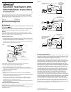
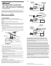
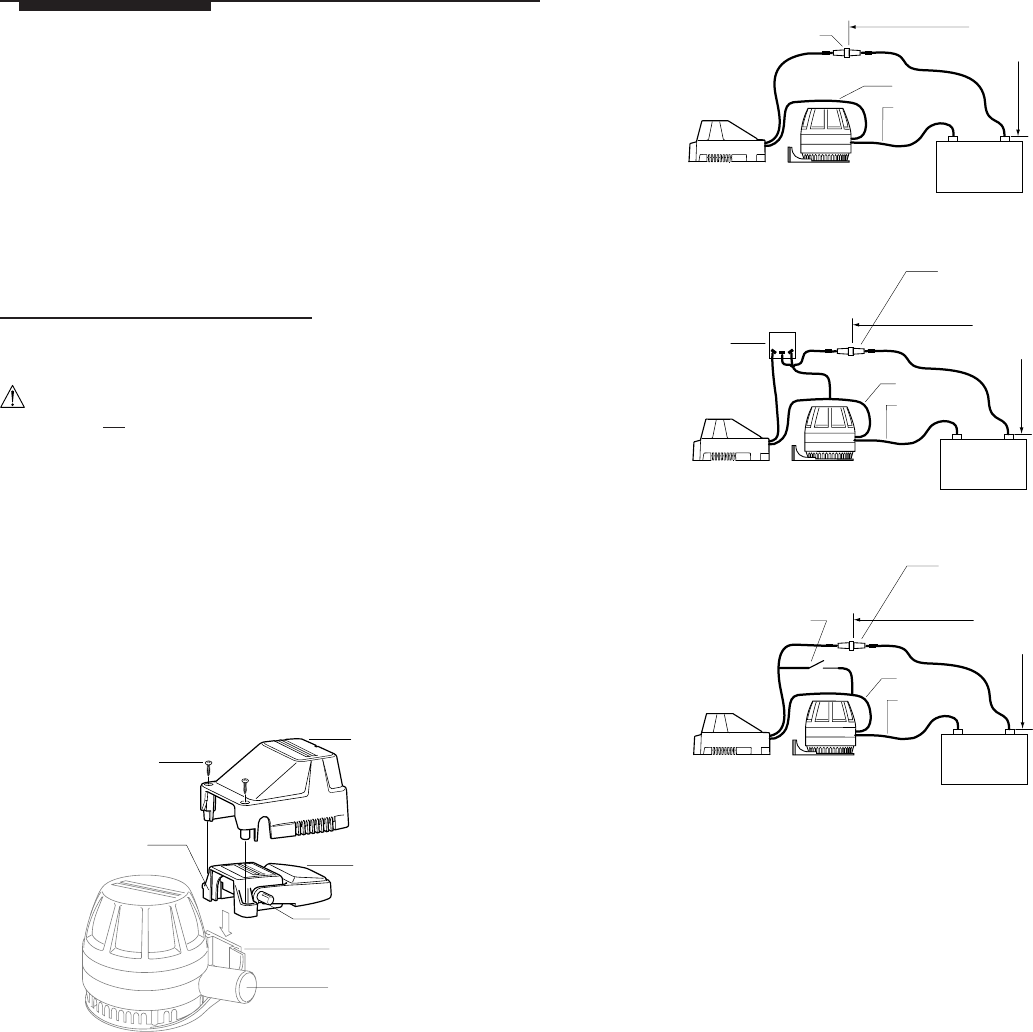
5. Wire float switch and bilge pump as shown in any one of the three diagrams.
Figure 2
Please note that in each case, float switch is in series (in-line) with pump and must
be connected to the positive (+) battery terminal.
The lead wires must terminate in a waterproof connection. Mount wires above
the highest possible water mark. For extra protection, liberally coat butt joints
and adjacent wire ends with liquid electrical tape.
Failure to properly fuse and make the appropriate water-resistant connections will
void the product warranty.
CARE AND MAINTENANCE INSTRUCTIONS
Periodically remove cover and clear away any debris that has accumulated around and
under the float, around the float arms, and in the strainer slots.
Periodically check the electrical connections to ensure that they are waterproof and
mounted high and dry.
SAVE THESE INSTRUCTIONS
Form Number 69272 Rev. D 03-10
Automatic Float Switch 4201,
4202 Installation Instructions
3
®
Figure 2
Pump
Automatic
Float Switch
12 Volt Battery
–
+
Black Wire
FULLY AUTOMATIC OPERATION
Brown Wire
Fuse (See Pump
Specifications For Size)
•
•
72" (183 cm)
Maximum Length
From (+) Terminal
to Fuse Holder
•
“ON/AUTO” OPERATION
•
•
Pump
Automatic
Float Switch
Fuse (See Pump
Specifications for Size)
Two-Terminal, “On-Off” Type
Switch Can Be Attwood
Rocker, Push-Pull, or
Toggle Type
•
•
12 Volt Battery
–
+
Black Wire
Brown Wire
•
•
72" (183 cm)
Maximum Length
From (+) Terminal
to Fuse Holder
“ON/OFF/AUTO” OPERATION
Pump
Automatic
Float Switch
Fuse (See Pump
Specifications for Size)
Attwood
Rocker Switch
(Rear View)
•
•
12 Volt Battery
–
Black Wire
Brown Wire
•
•
72" (183 cm)
Maximum Length
From (+) Terminal
to Fuse Holder
ATTWOOD LIMITED WARRANTY
ATTWOOD CORPORATION, 1016 North Monroe, Lowell, Michigan 49331, (“Attwood”),
warrants to the original consumer purchaser that this Attwood Float Switch will be free
from defects in materials and workmanship under normal use and service for a period
of three (3) years from the date of original consumer purchase.
This warranty does not extend to any batteries or fuses used with the float switch.
This limited warranty is not applicable if the float switch has been damaged by accident,
improper installation, unreasonable use, lack of proper maintenance, unauthorized
repairs or modifications, or other causes not arising out of defects in materials or
workmanship. Attwood's obligations under this warranty are limited to repair of the
product at Attwood's plant or replacement of the product at Attwood's option and at
Attwood's expense. Any expenses involved in the removal, reinstallation, or transportation
of the product are not covered by this warranty. The product must be returned to
Attwood's plant at the address indicated above postage prepaid, with proof of original
purchase including date. If Attwood is unable to replace the float switch and repair is
not commercially practicable or cannot be timely made, or if the original consumer
purchaser is willing to accept a refund in lieu of repair or replacement, Attwood may
refund the purchase price, less an amount for depreciation. The acceptance by
Attwood of any product returned or any refund provided by Attwood shall not be
deemed an admission that the product is defective or in violation of any warranty.
THIS WARRANTY IS ATTWOOD'S ONLY EXPRESS WARRANTY OF THIS PRODUCT.
NO IMPLIED WARRANTY SHALL EXTEND BEYOND THREE (3) YEARS FROM THE
DATE OF ORIGINAL CONSUMER PURCHASE. ATTWOOD SHALL NOT BE LIABLE
FOR ANY DAMAGES FOR LOSS OF USE OF THIS PRODUCT, NOR FOR ANY
OTHER INCIDENTAL OR CONSEQUENTIAL DAMAGES, COSTS OR EXPENSES.
Some states do not allow limitations on how long an implied warranty lasts or the
exclusion or limitation of incidental or consequential damages, so the above limitations
and exclusions may not apply to you. This warranty gives you specific legal rights and
you may have other rights which may vary from state to state.
© 2003 Attwood Corporation
1016 N. Monroe Street, Lowell, MI 49331-0260 www.attwoodmarine.com
Figure 1
Front Tabs
on Switch
#8 Stainless
Steel Screws
Cover
Automatic
Float Switch
Test Knob
Rear Slots
on Pump Bracket
Attwood V-Series Pump
•
•
•
•
•
•
•