


3
®
Attwood marine hardware, navigational lighting, bilge pumps, and other
marine accessories are specified more than any other brand by America’s
best-known boat manufacturers as original equipment. Look to Attwood
for quality replacement parts and marine accessories.
SAVE THESE INSTRUCTIONS
Form Number 69274 Rev. K 98-08
Deluxe Shower Sump System
4137, 4138 Mounting Instructions
The Attwood Deluxe Shower Sump System is an efficient, low cost system
incorporating an Attwood 750 GPH Pump and an Attwood Automatic Float
Switch. This system is designed to satisfy the needs of the boater for a
functional means of transferring “gray” water from the shower, or other
water drains. Multiple inlets can be hooked up to more than one drain with
different hose size options. The see-through top on the box allows you to
see when the filter needs cleaning.
Refer to the chart below to ensure that you have selected the proper shower
sump for your boat application:
Shower Sump D.C. Voltage D.C. Amps Max Fuse
Model Amperages
4137 12.0 2.7 4
4138 24.0 1.8 2
WARNING:
To prevent personal injury, never use 120/240 VAC power tools while
working in water or a wet environment.
To prevent personal injury, always disconnect the power source before
servicing or installing this product.
Always use the fuse amperage rating specified for this shower sump model.
Failure to do so could result in serious personal injury or fire hazards.
To prevent possible injury and water damage, shut off all water before servicing.
REQUIRED FOR INSTALLATION
• Fine-tooth hacksaw or
band saw
• File
• Drill and suitable drill bit
• Four #8 screws for
hold-down clamps
• Phillips screwdriver
• One hose clamp for each
hose used
• Wire connectors for
16-gauge wire
• See amperage in chart above
Optional:
• Attwood model 7615 switch or equivalent
Note:
Switch is recommended to allow the pump to be turned off in
an emergency
The following materials are needed if no sump pump mounting pad is in place:
• 1/2" (1.27) thick marine plywood
block large enough to mount
sump pump
• Hand-held roller
• Fiberglass—18 oz. mat or woven
roving
• Polyester resin and catalyst
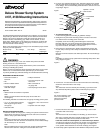
Cover
Optional 1/4" Vent
Hole Location
Float Switch
FilterPump
Box
Inlets
Outlet
•
•
•
•
•
•
•
•
•
Hold-Down Clamps
•
•
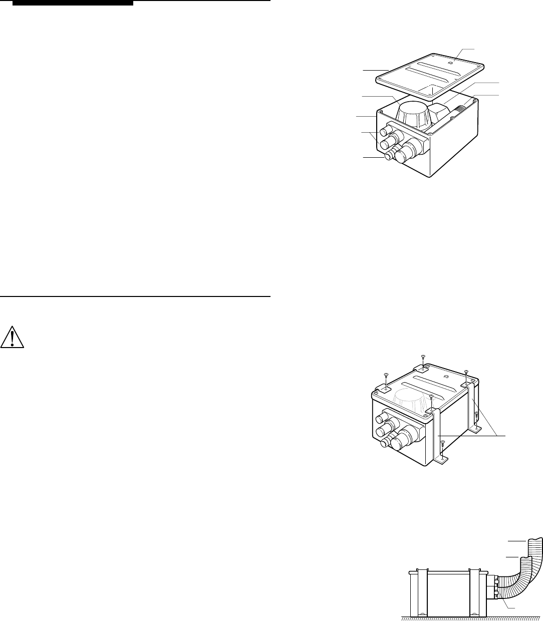
Inlet Hose(s)
Outlet Hose
Hose Clamp
•
•
•
For correct operation, outlet
hose must continually rise
above pump outlet to
prevent air-lock
INSTALLATION INSTRUCTIONS
1. Determine location of sump system, making sure system is lower than the
shower drain. Ensure there is enough structure and room to accommo-
date the sump system before drilling.
Note:
For correct operation of the automatic float switch, the box should be
mounted level. If the box cannot be mounted level, the end without fittings
can be raised up to 1/2" from level.
Note:
Because sailboats tend to heel, install sump system parallel lengthwise
with the bow-to-stern line. Fitting end can face either fore or aft.
2. For hook-up to multiple inlets/hose sizes, determine opening sizes needed
and saw ends off the correct fittings (sizes and cut locations are marked
on the fittings). File around the fitting inside diameter to remove burrs and
rough edges. Figure 1
3. To install mounting pad:
Locate mounting pad area according to guidelines in Step 1.
4. Sand gelcoat or paint off the mounting surface to create an area that
is 3" wider than the mounting pad on each side.
Completely cover the mounting pad with fiberglass. Saturate the
fiberglass with resin, and press the fiberglass edges down against
the hull to adhere the pad in place. Roll out the fiberglass to remove
any uneven surfaces, air bubbles, or excess resin.
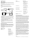
5. Place the box in desired location. Position the hold-down clamps (two
on each side) so the top of the clamps are between the two raised ribs.
Figure 2
Mark the screw hole locations and drill the pilot holes.
Do not drill through
the hull!
Note:
If possible, pre-wire the sump system before fastening clamps down. See
wiring diagram. Figure 4
6. Connect 3/4" I.D. outlet hose from thru-hull connector to the outlet fitting.
Secure the connection with a hose clamp.
Note:
The outlet hose must rise smoothly from the fitting, up to the thru-hull.
Any downward dip will trap water and air inside the pump. Figure 3
Figure 2
Figure 1
Figure 3
7. Connect inlet hoses from the drains to the inlet fittings. Secure each
connection with a hose clamp.
Note:
The inlet hoses must rise smoothly from the fitting, up to their Drains.
Also, using a shower drain with a trap will not allow air to vent out of the
box, and the rising water will not activate the float switch.
If the hose cannot be routed upward, or a drain with trap is desired:
Vent the sump system box by removing the system cover and drilling a 1/
4" hole where indicated. File away any rough edges, and replace the
cover (position hole toward the box end with no fittings). See Figure 1
8. Fasten sump system in place with the four hold-down clamps and four screws.