


14
Servicing should only be performed by a Qualifi ed Service Agent
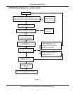
OPERATION AND SERVICE
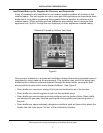
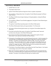
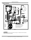
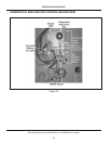
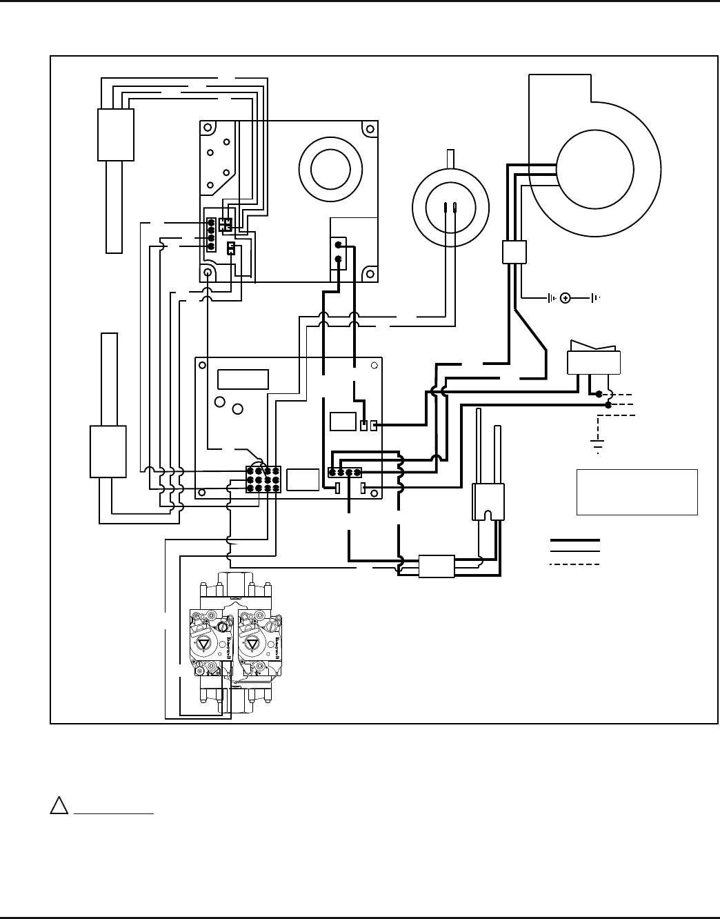
WIRING DIAGRAM
THERMOSTAT
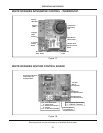
IGNITION BOARD
UPPER
PROBE/
PROBE
THERMOPLASTIC OR EQUIVALENT.
MUST BE REPLACED USE ONLY TYPE 105 C
IF ANY OF THE ORIGINAL WIRE AS SUPPLIED
BOARD, DIGITAL THERMOSTAT AND CONTROLS.
WHEN EQUIPPED WITH WHITE-RODGERS IGNITION
WIRING DIAGRAM FOR (A)BCG385T500-8N/8P
BY INSTALLER
FACTORY INSTALLED
120 VAC CIRCUIT
1a 1 1b
W - WHITE
BL - BLUE
G - GREEN
Y - YELLOW
R - RED
BR - BROWN
BK - BLACK
GROUND
TO EARTH
EARTH GROUND
NEUTRAL
HOT 120 VAC
BK
W
Y
Y
W
R
R
R
R
BL
BR
G
R
R
BK
Y
W
R
R
BK
BK
SENSOR
IGNITER/FLAME
LOWER
ECO
BLOWER PROVER
PRESSURE SWITCH
INDUCER
OFF
IN
PSI
IN
PSI
OFF
ON
ON
NOTE:
Must be properly grounded
and have correct polarity
connections.
Figure 10
!
WARNING
Disconnect from electrical supply before servicing unit. Replace all doors and panels
before operating the water heater.