


17
Servicing should only be performed by a Qualifi ed Service Agent
OPERATION AND SERVICE
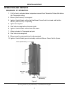
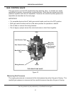
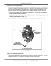
Manifold Pressure Adjustment
The main gas regulators are found beneath the silver or black cap screws. (Natural Gas
valves have silver caps; Propane valves have a black caps). Remove the caps to access
the outlet (manifold) pressure adjustment screw. IMPOR
TANT: Ensure that the outlet
pressure matches the manifold pressure that is listed on the water heater rating plate.
Natural Gas valves are factory preset to 3.5 inches W.C. The full rate outlet pressure •
range is between 3 and 5 inches W.C.
Propane (LP) valves are factory preset to • 10.0 inches W.C. The full rate outlet pressure
range is between 8 and 12 inches W.C.
Caution:
Always test the manifold pressure at the outlet when the gas is flowing.•
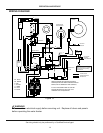
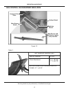
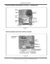
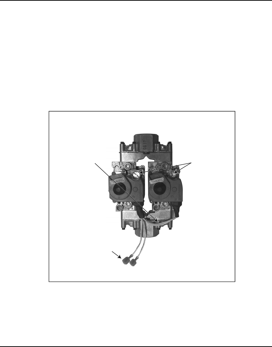
Wiring Harness
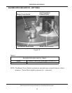
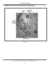
TOP VIEW OF GAS VALVE
Main Gas
Regulators
(Outlet Pressure
Adjustment)
Lead Wires
(24-Volt Main Valve
Solenoid Connections)
Figure 13
Main Valve Solenoid Connections
The figure above shows the two 24-volt main valve (MV) solenoid connections. The two
yellow wires from the 12-pin ignition board plug connect to these leads.