


10
WATER SYSTEM PIPING
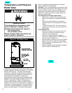
Tempering Valve Installation
A Tempering Valve should be installed per the manufac-
turer’s instructions in the hot water line. See Figure 5
(below) for sample tempering valve installation.
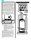
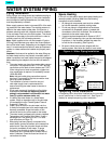
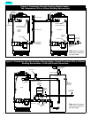
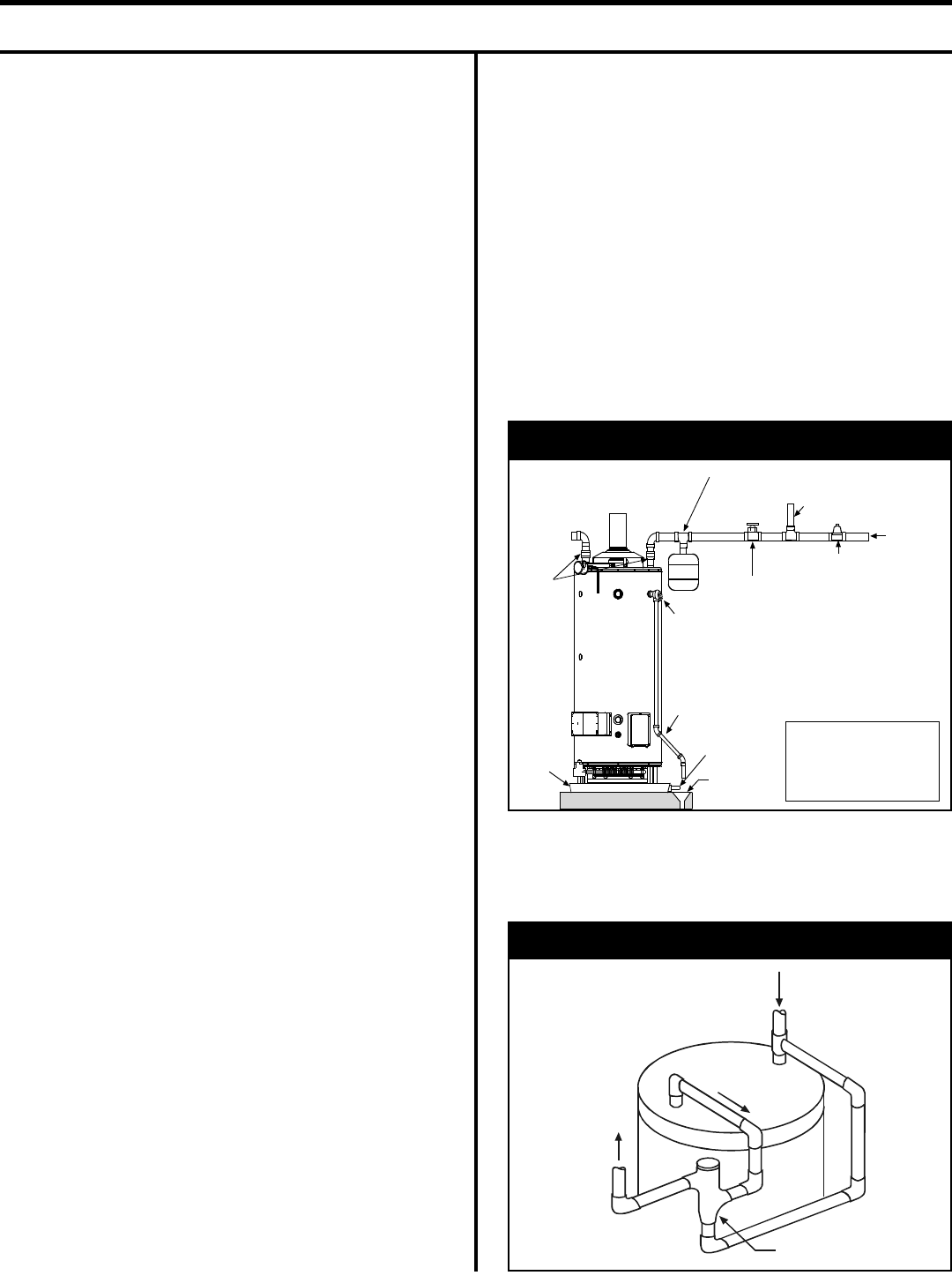
Piping Installation
Piping, fittings, and valves should be installed according to
the installation drawing (Figure 4). If the indoor installation
area is subject to freezing temperatures, the water piping
must be protected by insulation.
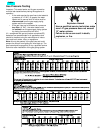
Water supply pressure should not exceed 80% of the work-
ing pressure of the water heater. The working pressure is
stated on the water heater’s data plate. If this occurs, a
pressure reducing valve with a bypass should be installed
in the cold water inlet line to the entire system. This should
be placed on the supply to the entire structure in order to
maintain equal hot and cold water pressures.
Note: Water supplied to the unit that exceeds 12 grains
(205 mg/l) total hardness may reduce the life and perform-
ance of the water heater. Depending on the degree of hard-
ness, it is recommended that either a water pre-treatment
system or a water softener be installed and properly main-
tained.
Important: Heat cannot be applied to the water fittings on
the water heater as they may contain nonmetallic parts. If
solder connections are used, solder the pipe to the adapter
before attaching the adapter to the hot and cold water fit-
tings.
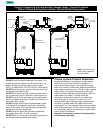
1. The water heater may have three water piping connec-
tion points. The top and front are 1 1/2” NPT and the
connections on the back of some heaters are 2” NPT.
When using front or back connections a nipple inlet
tube combination is required. For availability contact
1-800-456-9805.
Note: Inlet and outlet piping connections cannot
be mixed. For example, a top inlet connection must
use a top outlet connection.
2. The installation of unions in both the hot and
cold water supply lines is recommended for
ease of removing the water heater for service or
replacement.
3. Since most commercial installations utilize higher
temperatures, the use of a tempering valve is
strongly recommended in all domestic hot water
lines (i.e. public restroom sinks, etc).
4. If installing the water heater in a closed water
system, install an expansion tank in the cold water
line as specified under “Closed System/Thermal
Expansion” (Page 12).
5. Install a shut-off valve in the cold water inlet line.
It should be located close to the water heater and
be easily accessible. Know the location of this
valve and how to shut off the water to the heater.
6. The water heater is shipped with a factory-installed
Temperature and Pressure Relief Valve. Install a
discharge line in the opening in the T & P valve
(see instructions on Page 13).
7. After piping has been properly connected to the
water heater, remove the aerator at the nearest hot
water faucet. Open the hot water faucet and allow
the tank to completely fill with water. To purge
the lines of any excess air, keep the hot water
faucet open for 3 minutes after a constant flow of
water is obtained. Close the faucet and check all
connections for leaks.
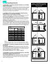
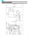
Figure: 4 Water Piping Installation
Hot Water
Outlet
Unions
Cold Water
Inlet Valve
Discharge line
6” max. above
drain
Cold Water
Supply to Fixtures
In a closed system use a
Thermal Expansion Tank
Temperature and
Pressure Relief Valve
Drain line
3/4” ID min.
Drain
Metal drain
pan 1 3/4”
depth max.
Pressure Reducing
Valve with Bypass
Main Water
Supply
Massachusetts:
Install a vacuum relief
in cold water line per
section 19MGL 142
Space Heating
If this unit is to be used to supply both space heating and
domestic potable (drinking) water then the following
instructions must be followed:
1. All piping and components used must be suitable
for use with domestic (potable) drinking water.
2. Do not use piping or components that have been
connected to a nonpotable system or treated with
chromates or other toxic chemicals. Do not add any
chemicals to the water heater piping.
3. If system requires temperatures in excess of 120°F
(49°C) install a tempering valve, per the manufacturers
instructions, in the domestic (potable) hot water line
to limit the risk of scalding (See Figure 5).
4. Be sure to follow the manual(s) shipped with the
heating system. Also follow any state or local codes.
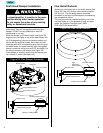
Figure 5: Tempering Valve
Follow the tempering
valve manufacturer’s
instructions.
Cold
Water
Inlet
Hot
Water
Outlet
Tempered water
to fixtures
Tempering valve
(Set to 120°F)
Index