


12
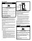
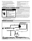
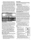
FIGURE 10A
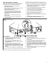
Temperature and Pressure
Relief Valve Installation
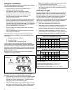
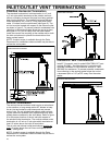
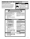
T&P Valve and Pipe Insulation (Some Models)
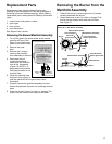
1. Locate the T&P Valve on the water heater.
2. Locate the slit running the length of the insulation.
3 Spread this slit open and slip it over the T&P Valve. See
Figure 10B. Apply gentle pressure to the insulation to
ensure it is fully seated on the T&P Valve. Once sealed
secure the insulation with a section of tape.
IMPORTANT: The insulation or tape should not block
or cover the T&P drain opening. Also the insulation or
tape should not block or hinder access to the T&P valve
manual relief lever.
4. Next locate the hot water (outlet) & cold water (inlet) pipes
to the water heater.
5. Select one of the sections of pipe insulation and locate the
slit that runs the length of the insulation.
6. Spread the slit open at the base of the insulation and slip
it over the cold water (inlet) pipe. Apply gentle
pressure along the length of the insulation to ensure it is
fully seated around the cold water pipe. Also ensure that
the base of insulation is flush with the water heater. Once
seated secure the insulation with a section of tape.
7. Repeat steps 5 through 6 for the hot water (outlet) pipe.
T&P Valve
T&P Valve
Drain Line
Manual Relief Lever
T&P Insulation
Figure 10B
T&P Valve Insulation
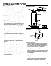
Closed System/Thermal Expansion
CAUTION - PROPERTY DAMAGE HAZARD
Periodic discharge of the temperature and pressure
relief valve may be due to thermal expansion in a closed
water supply system. The water utility supply meter
may contain a check valve, backfl ow preventer or water
pressure reducing valve. This will create a closed water
system. During the heating cycle of the water heater, the
water expands causing pressure inside the water heater
to increase. This may cause the temperature and pressure
relief valve to discharge small quantities of hot water. This
is an unacceptable condition and must be corrected. To
prevent this, it is recommended that a diaphragm-type
expansion tank (suitable for potable water) be installed
on the cold water supply line. The expansion tank must
have a minimum capacity of 1.5 U.S. gallons for every 50
gallons of stored water. Contact the local water supplier
or plumbing inspector for information on other methods to
control this situation.
Temperature and Pressure
Relief Valve
Explosion Hazard
If the temperature and pressure relief valve
is dripping or leaking, have a qualified
person replace it.
Examples of a qualified person include:
licensed plumbers, authorized gas company
personnel, and authorized service
personnel.
Do not plug valve.
Do not remove valve.
Failure to follow these instructions can
result in death, or explosion.
WARNING
For protection against excessive pressures and
temperatures, a temperature and pressure relief valve must
be installed in the opening marked “T & P RELIEF VALVE”
(see Figure 10A.) This valve must be design certifi ed by
a nationally recognized testing laboratory that maintains
periodic inspection of the production of listed equipment
or materials as meeting the requirements for Relief
Valves for Hot Water Supply Systems, ANSI Z21.22. The
function of the temperature and pressure relief valve is to
discharge water in large quantities in the event of excessive
temperature or pressure developing in the water heater.
The valve’s relief pressure must not exceed the working
pressure of the water heater as stated on the data plate.
IMPORTANT: Only a new temperature and pressure relief
valve should be used with your water heater. Do not use an
old or existing valve as it may be damaged or not adequate
for the working pressure of the new water heater. Do not
place any valve between the relief valve and the tank.
Drain Pan
Discharge line 3/4” min.
Do not cap or plug.
Temperature and
Pressure Relief Valve
Drain
6” max.