


4
Servicing should only be performed by a Qualied Service Technician
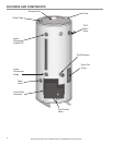
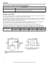
INSTALLATION CONSIDERATIONS
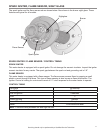
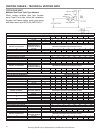
GAS AND ELECTRICAL CHARACTERISTICS
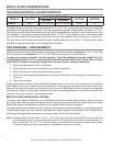
MODELS GAS TYPE
GAS SUPPLY PRESSURE
VOLTS/HZ AMPERES
MINIMUM MAXIMUM
All Models Natural 3.5" WC (0.87 kPa) 14.0" WC (3.48 kPa) 120/60 < 5
All models require a minimum gas supply pressure of 3.5” W.C. The minimum supply pressure is measured
while gas is flowing (dynamic pressure). The supply pressure (dynamic) should never fall below 3.5” W.C.
The supply pressure should be measured with all gas fired appliances connected to the common main firing
at full capacity. If the supply pressure drops more than 1.5” W.C. as gas begins to flow to the water heater
then the supply gas system including the gas line and/or the gas regulator may be restricted or undersized.
The gas valve on all models has a maximum gas supply pressure limit of 14" W.C. The maximum supply
pressure is measured while gas is not flowing (static pressure).
GAS PRESSURE – REQUIREMENTS
Main line gas pressure to the water heater for natural gas should be between a maximum of 14" w.c. (3.48 kPa)
static pressure and a minimum of 3.5" w.c. (0.87 kPa) dynamic pressure for Natural Gas.
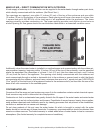
A supply gas pressure regulator ( service regulator ) must be installed on the gas supply line if the
static pressure exceeds 14” w.c. and it should be installed no closer than 3 feet (1 meter), but no farther
than 8 feet (2.4 meters) of equivalent length from the water heater’s inlet gas connection.
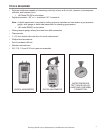
1. Check gas line pressure with a manometer.
2. Cycle the burner on and off several times to check its operation.
3. Check the operation of the limit and operating controls.
4. Check the vent system seams and joints and ensure that there is no discharge of flue products into
the room.
5. Check the input rate.
Supply gas pressure shall be measured while the water heater is not firing (static pressure) and while the
water heater is firing at full capacity (dynamic pressure). If the supply gas pressure to the water heater is not
between the required minimum and maximum values given in table above, adjust the supply gas regulator
as necessary. Adjust the supply gas regulator(s) per the regulator manufacturer’s instructions to achieve the
required “static” and “dynamic” supply gas pressure.
MULTIPLE APPLIANCE INSTALLATIONS:
In multiple water heater installations or in installations where the installed water heater(s) share a common
gas supply main with other gas fired appliances; the supply gas pressures shall be measured at each water
heater with all gas fired appliances connected to a common main firing at full capacity.
In multiple water heater installations the supply gas line regulators shall be adjusted to provide gas pressure
to each water heater within the minimum and maximum supply pressure requirements listed in table above
with all gas fired appliances connected to a common gas main firing at full capacity.
Note: A pressure drop of more than 1.5” W. C. (0.37 kPa) when the main burner ignites is an indication of
an inadequate supply of gas and can lead to ignition failure, rough starts and/or rough operation. If a
drop of more than 1.5” W. C. (0.37 kPa) in supply gas pressure occurs when the main burner ignites,
ensure the supply gas lines and regulator(s) are properly sized and installed.