


28
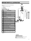
Removing and Replacing the Gas
Control Valve/Thermostat
IMPORTANT: The gas control valve/thermostat is a standard
valve with wire leads that connect to a thermal switch, flue
damper, igniter, and flammable vapor sensor
Removing the Gas Control Valve/Thermostat:
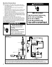
1. Turn off the gas at the manual shut-off valve on the gas
supply pipe (Figure 5).
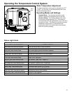
2. Move the ON/OFF switch on the gas control valve/
thermostat to the “OFF” position to turn off the water
heater and unplug from the wall outlet. (Figure 22).
3. Drain the water heater. Refer to the section of “Draining
and Flushing” and follow the procedure.
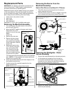
4. Disconnect the wire harness, flammable vapor sensor
wires, and igniter wire from the gas control valve/
thermostat. Disconnect pilot tube (7/16” wrench) and
manifold tube (3/4” wrench) at the gas control valve/
thermostat (Figure 27). NOTE: L.P. Gas systems use
reverse (left-hand) threads on the manifold tube.
5. Refer to “Gas Piping” (Figure 5) and disconnect the
ground joint union in the gas piping. Disconnect the
remaining pipe from the gas control valve/thermostat.
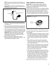
6. To remove the gas control valve/thermostat, thread a 4”
section of gas pipe into the inlet and use it to turn the
gas control valve/thermostat (counterclockwise.) Do not
use pipe wrench or equivalent to grip body. Damage
may result, causing leaks. Do not insert any sharp
Flame Guard
™
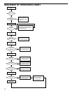
Safety System Operational Checklist
TROUBLESHOOTING CHART
objects into the inlet or outlet connections. Damage to
the gas control valve/thermostat may result.
Gas Control Valve/Thermostat:
To replace the gas control valve/thermostat, reassemble
in reverse order. When replacing the gas control valve/
thermostat, thread a 4” section of gas pipe into the inlet and
use it to turn the gas control valve/thermostat (clockwise.)
DO NOT OVER TIGHTEN, damage may result.
• Be sure to use approved Teflon® tape or pipe joint
compound on the gas piping connections and fitting on
the back of the gas control valve that screws into tank.
• Be sure to remove the pilot ferrule nut from the new gas
control valve/thermostat.
• Turn the gas supply on and check for leaks. Test the
water heater by brushing on an approved noncorrosive
leak detection solution. Bubbles forming indicate a leak.
Correct any leak found.
• Be sure tank is completely filled with water before
lighting and activating the water heater. Follow the
“Lighting Instructions” on page 16.
• With the burner lit, check the gas control valve/
thermostat supply line, manifold component block,
manifold tube, and pilot tube connections for
leaks. Check for leaks by brushing on an approved
noncorrosive leak detection solution. Bubbles forming
indicate a leak. Correct any leak found. IMPORTANT:
All leaks must be fixed immediately
• If additional information is required, contact the Service
Department at: 1-877-817-6750.
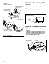
5. No leaks at pilot and manifold connection.
6. Manifold door screws securely tightened.
7. Depress the button on the thermal switch.
1. Manifold gasket properly sealed.
2. Viewport not damaged or cracked.
3. Flame-trap free of debris and undamaged.
4. Manifold component block properly installed.
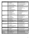
PROBLEM POSSIBLE CAUSE(S) CORRECTIVE ACTION
BURNER WILL NOT IGNITE 1. Pilot will not light
2. Thermostat set too low
3. No gas
4. Dirt in the gas lines
5. Pilot line clogged
6. Main burner line clogged
7. Non-functioning gas control valve/thermostat
8. Heater installed in a confined area
9. Flue Damper not functioning
1. See PILOT WILL NOT LIGHT OR REMAIN
LIT
2. Turn temp. dial to desired temperature
3. Check with gas utility company
4. Notify utility-install trap in gas line
5. Clean, locate source and correct
6. Clean, locate source and correct
7. Replace gas control valve/thermostat
8. Provide fresh air ventilation
9. Cycle power to the water heater off and on. If
problem persists replace the flue damper
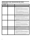
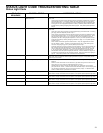
PILOT WILL NOT LIGHT OR
REMAIN LIT
1. Non-functioning Pilot\Igniter-Flame Sensor
2. The thermal switch tripped
3. Igniter wire connection loose
4. Air in gas line
5. Low gas pressure
6. No gas
7. Dirt in gas lines
8. Cold drafts
9. Thermostat ECO switch open
10. Pilot line or orifice clogged
11. Air for combustion obstructed
12. FV Senor Lockout
13. Flue Damper not functioning
1. See Status Light Code Troubleshooting Table
section
2. See Pilot Light Troubleshooting Flowchart
section
3. Seat connector firmly in socket
4. Bleed the air from the gas line
5. Check with gas utility company
6. Check with gas utility company
7. Notify utility-install dirt trap in gas line
8. Locate source and correct
9. Replace thermostat
10. Clean, locate source and correct
11. See maintenance section for inspection and
cleaning of flame trap.
12. Contact a qualified person to reset the sensor
13. Cycle power to the water heater off and on. If
problem persists replace the flue damper