


20
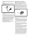
Electrical Connections
Before plugging in the water heater, always make sure:
• The Voltage and frequency correspond to that specified
on the water heater.
• The electrical outlet has the proper overload fuse or
breaker protection.
• Water heater to be located within 6 feet of 120VAC outlet.
• Unit is to connect to a 120VAC electrical supply outlet
(extension cord is not allowed).
• The water heater and the outlet are properly grounded.
• Installed in accordance with prevailing provisions of local
codes, or in the absence of such, National Electric Code,
ANSI/NFPS 70 current edition.
Completely fill the tank with water and check all
connections for leaks. Open the nearest hot water faucet
and let it run for three (3) minutes to purge the water lines
of air and sediment and to ensure complete filling of the
tank. The Electrical power may then be turned on. Verify
proper operation after servicing.
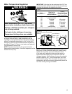
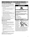
WARNING
WARNING
Electric Shock Hazard
Disconnect power before
servicing.
Replace all parts and panels
before operating.
Failure to do so can result in
death or electrical shock.
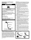
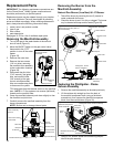
DAMPER
FLAME SENSOR\IGNITER
GAS CONTROL VALVE\THERMOSTAT
4 3 2 1
3 2 1
6 5 4
FV SENSOR
TEMPERATURE
CUT-OFF SWITCH
FLUE DAMPER
TRANSFORMER
1 2 3
4 5 6
BL
RD
YL
YL
BN - 24VAC
V - 24VAC
BK - 120VAC
WH - 120VAC
GR
BK - 24VAC (HOT)
WH - 24VAC (NEUTRAL)
BL
RD
BL
RD
YL
YL
BK - 24VAC (HOT)
WH - 24VAC (NEUTRAL)
YL - 24VAC
YL - 24VAC
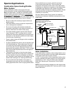
TRANSFORMER
YL 24 VAC
GAS CONTROL VALVE/
THERMOSTAT
FV SENSOR
IGNITER/FLAME
SENSOR
BK - 120VAC
W - 120VAC
YL 24 VAC
BK 24 VAC (H)
WH 24 VAC (N)
TEMPERATURE CUT-OFF
SWITCH
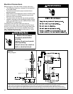
You must provide all wiring of the proper size outside of the water heater. You must obey local
codes and electric
utility requirements when you install this wiring.
This appliance must be electrically grounded in accordance with local codes or, in the absence of
local
codes, with the
National Electrical Code ANSI/NFPA No 70 (current edition) and/or THE CSA C22.1 ELECTRICAL CODE.(CURRENT EDITION)
Note: If any of the original wire as supplied with the appliance must be replaced, it
must be replaced with 105
°
C wire or its equivalent.
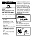
Caution: Label all wires prior to disconnection when servicing controls. Wiring errors can cause improper and dangerous operation.
YL
YL
ON/OFF SWITCH
END SWITCH
BN 24 VAC
V 24 VAC
Figure 23:
Wiring Diagram