


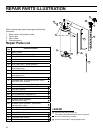


28
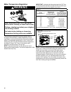
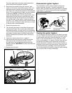
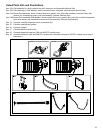
Flame Guard™ Safety System Operational Checklist
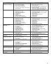
TROUBLESHOOTING CHART
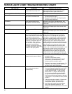
4. Manifold component block properly installed.
5. No leaks at pilot and manifold connection.
6. Burner door screws securely tightened.
1. Burner door gasket properly sealed.
2. Viewport not damaged or cracked.
3. Flame-trap free of debris and undamaged.
PROBLEM POSSIBLE CAUSE(S) CORRECTIVE ACTION
BURNER WILL NOT IGNITE 1. Pilot not lit
2. Thermostat set too low
3. No gas
4. Dirt in the gas lines
5. Pilot line clogged
6. Main burner line clogged
7. Non-functioning thermopile
8. Non-functioning thermostat
9. Heater installed in a confined area
1. Light pilot
2. Turn temp. dial to desired temperature
3. Check with gas utility company
4. Notify utility-install trap in gas line
5. Clean, locate source and correct
6. Clean, locate source and correct
7. Replace thermopile
8. Replace thermostat
9. Provide fresh air ventilation
SMELLY WATER 1. Sulfides in the water 1. Replace the anode with a special anode
BURNER FLAME YELLOW-
LAZY
1. Insufficient secondary air
2. Low gas pressure
3. Flue clogged
4. Main burner line clogged
5. Heater installed in a confined area
6. Obstruction in main burner orifice
1. Provide ventilation to water heater
2. Check with gas utility company
3. Clean, locate source and correct
4. Clean, locate source and correct
5. Proper fresh air ventilation
6. Clean or replace orifice
PILOT WILL NOT LIGHT OR
REMAIN LIT
1. Non-functioning igniter
2. Thermopile connection loose
3. Air in gas line
4. Proper Lighting Sequence not followed.
Gas Control / Temperature Knob was not
held in for sufficient time.
5. Low gas pressure
6. No gas
7. Dirt in gas lines
8. Cold drafts
1. Replace igniter pilot assembly
2. Seat connector firmly in socket
3. Bleed the air from the gas line
4. Do not attempt to relight if the red light is lit
and the pilot flame is not visible through the
view port. Wait until the red light is no longer
lit, then follow lighting instructions on the water
heater.
5. Check with gas utility company
6. Check with gas utility company
7. Notify utility-install dirt trap in gas line
8. Locate source and correct
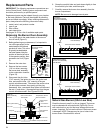
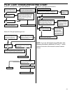
Removing and Replacing the Gas
Control Valve/Thermostat
Removing the Gas Control Valve/Thermostat:
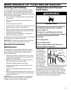
1. Turn the gas control/temperature knob to the “OFF”
position (Figure 19A).
2. Turn off the gas at the manual shut-off valve on the gas
supply pipe (Figure 3).
3. Drain the water heater. Refer to the section on “Draining
and Flushing” and follow the procedure.
4. Disconnect the igniter wire from the igniter lead wire.
Disconnect the temperature sensor wire, then use
needle nose pliers to disconnect the red (+) and white
(-) thermopile wires. Disconnect the pilot tube (7/16”
wrench) and manifold tube (3/4” wrench) at the gas
control valve/thermostat (Figure 22). Refer to “Gas
Piping” (Figure 3) and disconnect the ground joint union
in the gas piping. Disconnect the remaining pipe from
the gas control valve/thermostat.
5. To remove the gas control valve/thermostat, thread a 4”
section of gas pipe into the inlet and use it to turn the
gas control valve/thermostat (counterclockwise.) Do not
use a pipe wrench or equivalent to grip body. Damage
may result. Do not insert any sharp objects into the
inlet or outlet connections. Damage to the gas control
valve/thermostat may result.
Gas Control Valve/Thermostat:
To replace the gas control valve/thermostat, reassemble
in reverse order. When replacing the gas control valve/
thermostat, thread a 4” section of gas pipe into the inlet and
use it to turn the gas control valve/thermostat (clockwise.)
DO NOT OVER TIGHTEN, damage may result.
• Be sure to use approved Teflon® tape or pipe joint
compound on the gas piping connections and fitting on
the back of the gas control valve that screws into the
tank.
• Be sure to remove the pilot ferrule nut from the new gas
control valve/thermostat.
• Turn the main gas supply on and check the gas supply
connections for leaks. Use an approved noncorrosive
leak detection solution. If such a solution is not available,
use a mixture of hand dish washing soap and water (one
part soap to 15 parts water) or childrens’ soap bubble
solution. Bubbles forming indicate a leak. Correct any
leak found.
• Be sure tank is completely filled with water before
lighting and activating the water heater. Follow the
“Lighting Instructions” on page 17.
• With the pilot and main burner lit, check the manifold
tube and pilot tube connections for leaks. Correct any
leak found.
• If additional information is required, reference the
number on the cover of this manual for service
information.
TEFLON
®
is a registered trademark of E.I. Du Pont De Nemours and Company.