


27
if the door gasket does not create a seal between the
burner door and the combustion chamber.
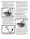
6. Reconnect the manifold tubing (3/4” wrench), pilot
tubing (7/16” wrench), temperature sensor wires, and
thermopile wires to the gas control valve/thermostat.
(See Figure 22 for the correct position of the thermopile
wires.) Do not cross-thread or apply any thread sealant
to the fittings. NOTE: If installing a new pilot tube
install the provided ferrule nut in the gas control valve/
thermostat at the pilot location, hand tight only. Next,
insert the pilot tube into the ferrule nut until it bottoms
out. Hold the tube in this position. Tighten the ferrule
nut with a 7/16” wrench until the crimp connection seals
to the pilot tube. Continue to tighten until the nut is tight
in the gas control valve/thermostat.
7. Reconnect the igniter wire.
8. Turn the main gas supply on and check the gas supply
connections for leaks. Use an approved noncorrosive
leak detection solution. If such a solution is not available,
use a mixture of hand dish washing soap and water (one
part soap to 15 parts water) or childrens’ soap bubble
solution. Bubbles forming indicate a leak. Correct any
leak found.
9. Follow the “Lighting Instructions” on page 17.
10. With the pilot and main burner lit, check the manifold
tube and pilot tube connections for leaks. Correct
any leak found. Use an approved noncorrosive leak
detection solution. IMPORTANT: All leaks must be fixed
immediately.
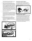
11. Replace the outer door
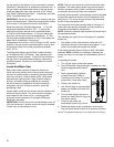
Figure 30A
Combustion Chamber
Door Gasket
Bracket
Flame-trap
Figure 30B
Close-up inside view of the combustion chamber
Bracket
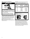
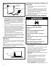
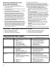
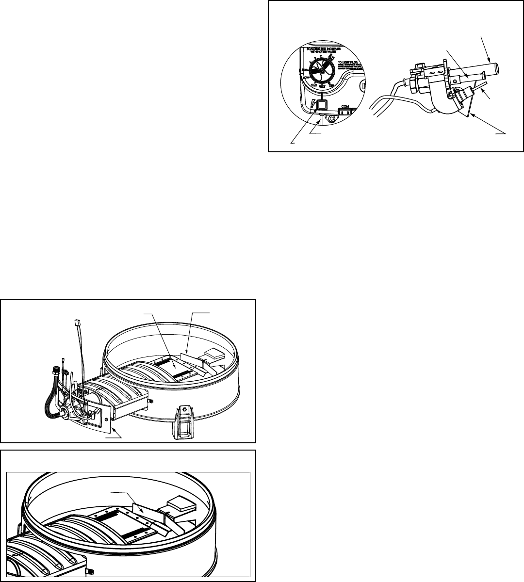
Piezoelectric Igniter System
The piezoelectric igniter system consists of the igniter
button, electrode, and wire. The pilot is ignited by an
electric spark generated when the igniter button is pressed.
(See Figure 31). Use only factory authorized piezoelectric
igniter parts for replacement.
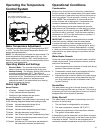
VAC
Pilot/Thermopile Bracket
(Opposite Side)
Electrode
Thermopile
Pilot
Igniter Button
Wire to Electrode
Figure 31
Gas Igniter Assembly
Testing the Igniter System
Turn off the gas to the water heater at the manual gas shut-
off valve. Watch the electrode tip while activating the igniter.
A visible spark should jump from the electrode. To avoid
shock, do not touch the burner or any metal part on the
pilot or pilot assembly. If no spark is visible, check the wire
connections and make sure the electrode is not broken.
Replace the igniter if defective. Dirt and rust on the pilot or
electrode tip can prevent the igniter spark. Wipe clean with
a damp cloth and dry completely. Rust can be removed
from the electrode tip and metal surfaces by lightly sanding
with an emery cloth or fine grit sandpaper.