


26
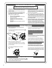
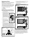
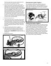
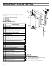
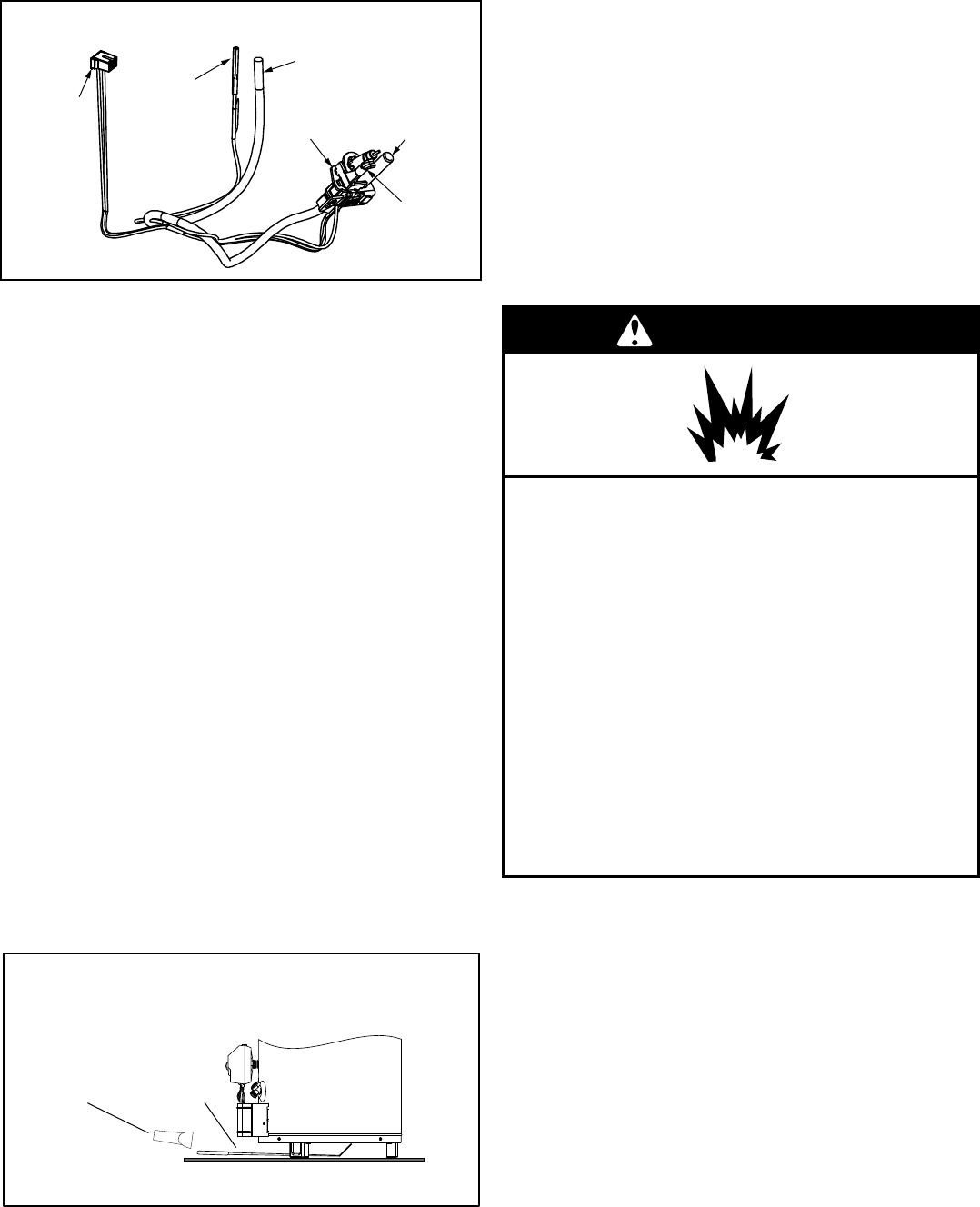
Pilot
Thermopile
Pilot/Thermopile
Assembly
Pilot Tube
(Ferrule Nut
Not Shown)
Igniter
Connector
Thermopile
Connectors
Figure 28
Pilot/Thermopile Assembly
(50K Models)
6. Push the new pilot/thermopile assembly connectors
through the opening in the burner door (See Figure 27).
Do not to scrape or nick the wires during installation.
IMPORTANT: DO NOT USE PILOT/THERMOPILES
WITH FIBERGLASS SLEEVES. The replacement kit
does not contain a fiberglass sleeve over the pilot/
thermopile wires.
7. Attach the pilot assembly to the Burner Door Assembly.
8. Position the new thermopile wires through the top
opening of the manifold component block (Figure 27).
Be sure that the igniter wire is positioned through the
middle opening of the manifold component block.
Position the pilot tube through the bottom opening of
the manifold component block.
9. See “Replacing the Burner Door Assembly” section.
NOTE: Use the ferrule nut supplied with the new pilot/
thermopile assembly when connecting the pilot tube to
the gas control valve/thermostat.
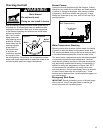
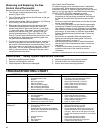
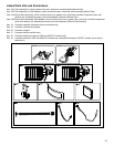
External Inspection & Cleaning of the
Flame-trap
Although not likely to occur, if debris collects on the flame-
trap, use a vacuum, compressed air, or a soft bristle brush
to remove it.
NOTE: If unable to inspect or clean the flame trap from
underneath, follow the “Cleaning the Combustion Chamber
and Flame-trap” section instructions.
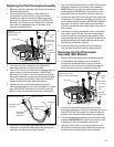
Figure 29
Flame-trap visual inspection
Mirror
Flashlight
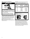
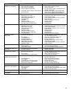
Cleaning the Combustion Chamber and
Flame-trap
1. Follow procedure outlined in “Removing the Burner
Door Assembly”.
2. Use a vacuum cleaner/shop vac to remove all loose
debris in the combustion chamber (Figure 30A). Use
compressed air to clear any dust or debris that may
have accumulated in the flame-trap.
3. Reassemble following the procedure under “Replacing
the Burner Door Assembly”.
Replacing the Burner Door Assembly
result in death, explosion, or fire.
WARNING
Replace manifold component block if missing
or removed.
Replace door gasket if damaged.
Failure to follow these instructions can
Replace viewport if glass is missing or
damaged.
Tighten both burner door screws
securely.
Explosion Hazard
Remove any fiberglass between gasket
and combustion chamber.
1. Check the door gasket for damage or imbedded debris
prior to installation.
2. Inspect the viewport for damage and replace as required.
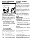
3. Insert the burner assembly into the burner
compartment, making sure that the burner assembly
sits firmly against the burner bracket inside the
combustion chamber (Figure 30B).
IMPORTANT:
Do not to scrape or nick the wires during
installation.
4. Inspect the door gasket and make sure there is no
fiberglass insulation between the gasket and the
combustion chamber.
5. Replace the two screws which secure the burner
assembly to the combustion chamber and tighten
securely. There should be no space between the
gasket part of the burner door and combustion
chamber. IMPORTANT: Do not operate the water heater