


24
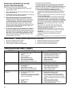
Replacement Parts
IMPORTANT: The following maintenance procedures are
for the Flame Guard™ Safety System components and
should be performed by a qualified person.
Replacement parts may be ordered through your plumber
or the local distributor. Parts will be shipped at prevailing
prices and billed accordingly. When ordering replacement
parts, always have the following information ready:
1. model, serial, and product number
2. type of gas
3. item number
4. parts description
See pages 31-32 for a list of available repair parts.
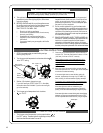
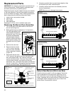
Removing the Burner Door Assembly
1. Turn off the gas to the water heater at the manual
shut-off valve (Figure 3).
2. Before performing any maintenance, it is important to
turn off the gas supply to the
water heater at the manual
gas shut-off valve. This valve
is typically located beside
the water heater. Note the
position of the shut-off valve
in the open/on position, then
proceed to turn it off (Figure
3).
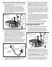
3. Remove the outer door.
4. Remove the two screws
(1/4” nut driver) securing
the burner door assembly
to the combustion chamber
(Figure 23).
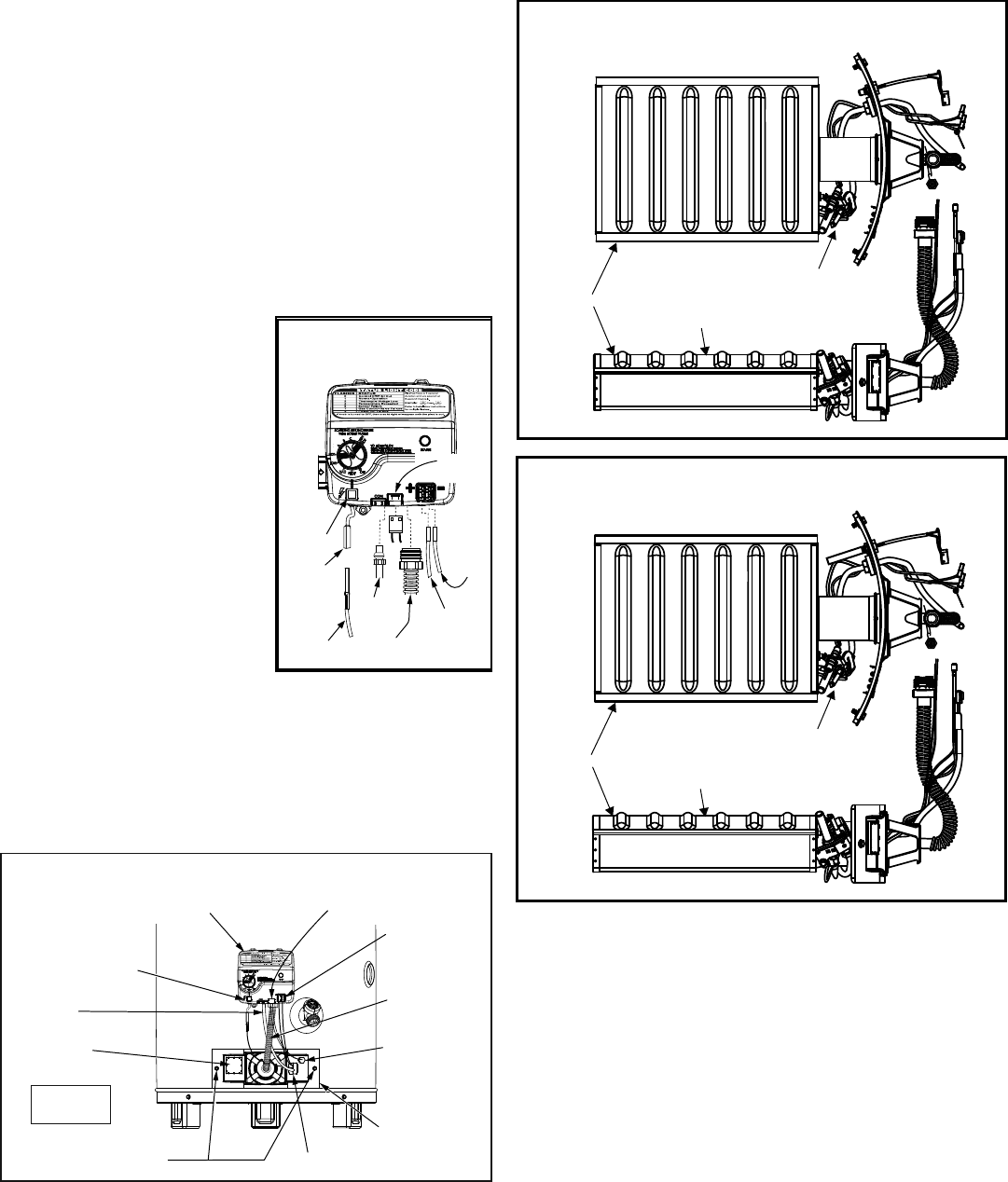
5. Disconnect the pilot tube
(7/16” wrench), the igniter wire from the igniter lead
wire, and manifold tube (3/4” wrench) at the gas
control valve/thermostat. Disconnect the sensor wires
(lift white lever outward, then gently pull the plug
downward). Also, use needle nose pliers to disconnect
the red (+) and white (-) thermopile wires from the gas
control valve/thermostat. See Figures 22 & 23.
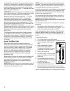
Figure 23
Burner Assembly
Removal
Burner Door Screws (2)
Manifold Component Block
Burner Door
Temperature
Sensor
Manifold Tube
Pilot Tube
Viewport
Thermopile
Wire
Connections
Piezo Igniter Button
Gas Control Valve/
Thermostat
Temperature Sensor
Wire Connection
Outer Door
Not Shown
VAC
Igniter
Wire
Red
Wire
(Left
Side)
Pilot
Tube
Manifold
Tube
Igniter
Button
Figure 22
Gas Control Valve/
Thermostat
Igniter
Lead
Wire
White
Wire
(Right
Side)
VAC
Sensor
Wires
6. Grasp the manifold tube and push down slightly to free
the manifold, pilot tube, and thermopile.
7. Carefully remove the burner door assembly from the
burner compartment.
NOTE: Be sure not to damage internal parts.
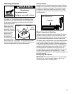
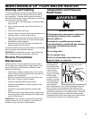
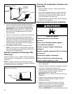
Figure24A
NaturalGas(LowNox)
Burner Door Assembly
Burner
Use brush on this surface.
Pilot Assembly
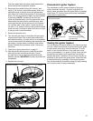
Figure24B
NaturalGas(LowNox)
Burner Door Assembly
50K Models
Burner
Use brush on this surface.
Pilot Assembly
Natural Gas Burner (Ultra Low Nox)
Check the burner to see if it is dirty or clogged. The burner
may be cleaned with soft paint brush (Figure 24). Do not
use a wire brush or any tool that may damage the burner
screen. Important: Do not use the burner if the burner screen
is damaged. NOTE: Damage may be rips or holes in the
burner screen. Discoloration is normal.