


11
Chimney Connection
IMPORTANT: Before connecting a vent to a chimney,
make sure the chimney passageway is clear and free of
obstructions. The chimney must be cleaned if previously
used for venting solid fuel appliances or fireplaces. Also
consult local and state codes for proper chimney sizing and
application or, in the absence of local and state codes, the
“National Fuel Gas Code”, ANSI Z223.1(NFPA 54)-current
edition.
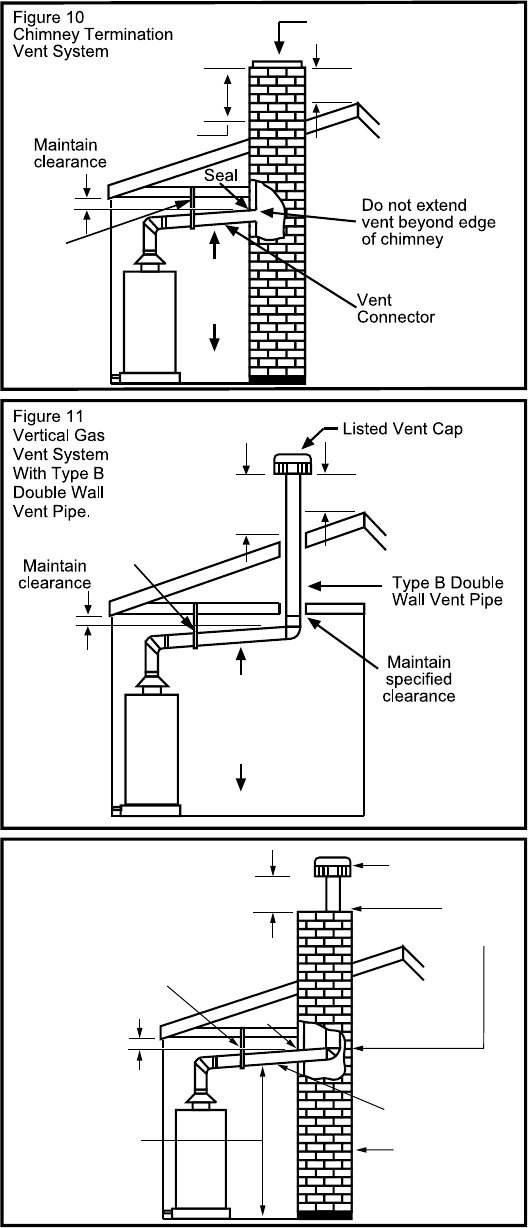
• The connector must be installed above the extreme
bottom of the chimney to prevent potentially blocking
the flue gases.
• The connector must be firmly attached and sealed to
prevent it from falling out.
• To aid in removing the connector, a thimble or slip joint
may be used.
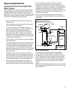
• The connector must not extend beyond the inner edge
of the chimney as it may restrict the space between it
and the opposite wall of the chimney (Figure 10).
Do not terminate the vent connector in a chimney that has
not been certified for this purpose. Some local codes may
prohibit the termination of vent connectors in a masonry
chimney.
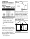
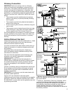
Vertical Exhaust Gas Vent
Vertical exhaust gas vents must be installed with U.L. listed
type B vent pipe according to the vent manufacturer’s
instructions and the terms of its listing.
It must be connected to the water heater’s draft hood by a
listed vent connector or by directly originating at the draft
hood opening.
Vertical gas vents must terminate with a listed cap or
other roof assembly and be installed according to their
manufacturer’s instructions.
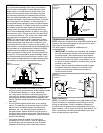
Gas vents must be supported to prevent damage, joint
separation, and maintain clearances to combustible
materials (Figures 11 and 12).
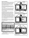
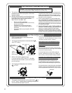
IMPORTANT: This gas vent must be terminated in a
vertical position to facilitate the removal of the burnt gases.
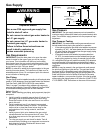
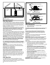
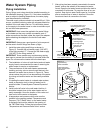
An unused chimney flue or masonry enclosure may be
used as a passageway for the installation of a gas vent
(Figure 12).
Common (combined) venting is allowable with vertical type
B vent systems and lined masonry chimneys as long as
proper draft for the water heater is established under all
conditions of operation.
IMPORTANT: Do not common vent this water heater with
any power vented appliance.
Figures 10-12 are examples of vent pipe system
installations and may or may not be typical for your specific
application. Consult the “National Fuel Gas Code”, NFPA
54, ANSI Z223.1-current edition and the guidelines set forth
by prevailing local codes.
*
Maintain vent pipe clearance requirements to local, state
and/or the “National Fuel Gas Code”, ANSI Z223.1(NFPA
54)-current edition.
**
NFPA 211, Standard for Chimneys, Fireplaces, Vents,
and Solid Fuel-Burning Appliances states that these
chimneys are intended to be installed in accordance with
the installation instructions provided with each chimney
support assembly. Minimum air space clearance to
combustible materials should be maintained as marked on
the chimney sections.
Slope up
1/4 in.
per ft.
minimum
3 ft. minimum
2 ft. minimum above any
object within10 ft.
horizontally
2 ft. minimum above any
object within10 ft.
horizontally
3 ft. minimum
Vent
connector
slope up
1/4 in. per ft.
minimum
*
*
**
Listed Lined
Chimney
Support Strap
Support
Strap
Figure 12
Venting Through
a Chimney
with Type B
Double Wall
Vent Pipe.
MAINTAIN MANUFACTURER’S
SPECIFIED MINIMUM CLEARANCE
LISTED VENT CAP
VENT CONNECTOR
UNUSED CHIMNEY
FLUE OR MASONRY
ENCLOSURE
SEAL
*MAINTAIN
CLEARANCE
VENT
CONNECTOR
SLOPE UP
1/4 IN. PER FT.
MINIMUM
**MAINTAIN
SPECIFIED
CLEARANCE
SUPPORT
STRAP