


10
Vent Pipe System
This water heater uses a non-direct, single-pipe vent system
to remove exhaust gases created by the burning of fossil fuels.
Air for combustion is taken from the immediate water heater
location or is ducted in from the outside (see “Combustion Air
Supply and Ventilation” section).
This water heater must be properly vented for the removal of
exhaust gases to the outside atmosphere. Correct installation
of the vent pipe system is mandatory for the proper and
efficient operation of this water heater and is an important
factor in the life of the unit.
The vent pipe must be installed according to all local and state
codes or, in the absence of local and state codes, the “National
Fuel Gas Code”, ANSI Z223.1(NFPA 54)-current edition. The
vent pipe installation must not be obstructed so as to prevent
the removal of exhaust gases to the outside atmosphere.
IMPORTANT: The use of vent dampers is not recommended
by the manufacturer of this water heater. Although some vent
dampers are certified by CSA International, this certification
applies to the vent damper device only and does not mean
they are certified for use on this water heater.
U.L. recognized fuel gas and carbon monoxide (CO) detectors
are recommended in all applications and should be installed
using the manufacturer’s instructions and local codes, rules, or
regulations.
IMPORTANT: If you lack the necessary skills required to
properly install this venting system, you should not proceed,
but get help from a qualified person.
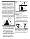
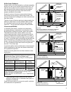
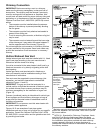
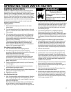
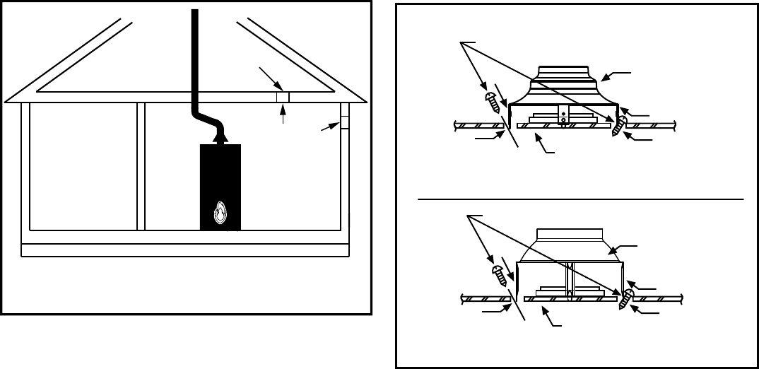
Draft Hood Installation
Align the legs of the draft hood with the slots provided.
Insert the legs and secure the draft hood to the water
heater’s top with the four screws provided as shown in
Figure 9. Do not alter the draft hood in any way. If you are
replacing an existing water heater, be sure to use the new
draft hood supplied with the water heater. IMPORTANT:
50K models must use the supplied 4” draft hood. See
Figure 9.
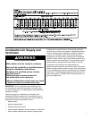
Vent Pipe Size
It is important that you follow the guidelines in these
instructions for sizing a vent pipe system. If a transition to
a larger vent size is required, the vent transition connection
must be made at the draft hood outlet.
Vent Connectors
1. Type B, Double wall, U.L. Listed Vent Pipe.
2. Single wall Vent Pipe.
Maintain the manufacturer’s specified minimum clearance from
combustible materials when using type B double wall vent
pipe.
Vent connectors made of type B, double wall vent pipe
material may pass through walls or partitions constructed
of combustible material if the minimum listed clearance is
maintained.
Maintain a six inch minimum clearance from all combustible
materials when using single wall vent pipe.
IMPORTANT: Single wall vent pipe cannot be used for water
heaters located in attics and may not pass through attic
spaces, crawl spaces or any confined or inaccessible location.
A single wall metal vent connector cannot pass through any
interior wall.
When installing a vent connector, please note the following:
• Install the vent connector avoiding unnecessary bends,
which create resistance to the flow of vent gases.
• Install without dips or sags with an upward slope of at least
1/4-inch per foot.
• Joints must be fastened by sheet metal screws or other
approved means. It must be supported to maintain
clearances and prevent separation of joints and damage.
• The length of the vent connector cannot exceed 75% of
the vertical vent height.
• The vent connector must be accessible for cleaning,
inspection, and replacement.
• Vent connectors cannot pass through any ceiling, floor,
firewall, or fire partition.
• It is recommended (but not mandatory) that a minimum 12
inches of vertical vent pipe be installed on the draft hood
prior to any elbow in the vent system to improve conditions
for positive flow of venting gases.
IMPORTANT: Existing vent systems must be inspected for
obstructions, corrosion, and proper installation.
Figure 9
Draft hood Inst allation
Sheet Metal Screws (four provided)
Draft hood
Jacket top
Install the draft hood with
the four screws provided.
Slot
Slot
Legs
Legs
Sheet Metal Screws (four provided)
Draft hood
Jacket top
Install the draft hood with
the four screws provided.
Slot
Slot
Legs
Legs
4” Draft Hood
(50K Models)
3”- 4” Draft Hood
Combination
Alternative
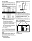
Opening
Location
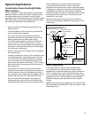
1 sq. Inch
Per 3000 BTU/HR
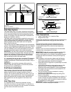
Confined
Space
Figure 8B
All Air from Outdoors
Using a Single Permanent Opening